Continue to Site

Welcome to EDAboard.com

Welcome to our site! EDAboard.com is an international Electronics Discussion Forum focused on EDA software, circuits, schematics, books, theory, papers, asic, pld, 8051, DSP, Network, RF, Analog Design, PCB, Service Manuals... and a whole lot more! To participate you need to register. Registration is free. Click here to register now.

Reason for the higher output voltage on the LLC transformer

Status
Not open for further replies.

Manikumar_s

Newbie
Joined
Dec 21, 2021
Messages
1
Helped
0
Reputation
0
Reaction score
0
Trophy points
1
Activity points
23
Converter : Half Bridge LLC Resonance Converter
Transformer: Turns ratio: 5:1 (pry turns: sec turns)
PSU gain : Resonant gain X Converter Gain X Transformer gain.
LLC Converter operates on Inductive region above resonance condition for all load condition to achieve ZVS.
Max resonant gain in this condition 1.
Converter gain for Half bridge LLC is 1/2 and full bridge was 1.
Transformer gain was 1/5. And I am operating with 50% fixed Duty cyle and Max switching freq of 1000KHz to min freq of 600KHZ.
For the above specification, When I give input voltage of 270V, My output voltage should be =>Vin X Resonant gain (1) X Converter gain (1/2) X TRF Gain (1/5)
Output voltage => 270X1X1/2X1/5,
=> 270/10
=> 27V
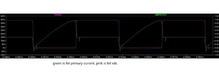
My Module output voltage should be 27V. But I am observing 28V output voltage for the 270V input at 30A output current (Converter operates in full load and Observed Switching freq was 690KHZ and my set Resonant freq was 480KHz)
Seems to be transformer gain was more than the estimated value. What may be reason for the above operation.
 

Attachments

  • Infineon-Design_example_resonant_LLC_converter_operation_and_design-AN-v01_00-EN.pdf
    1.2 MB · Views: 121

as you move down towards resonance, Vout will rise, you can reduce Lmag slightly, or increase Lseries-resonant, or lift frequency .....
 

Also, if you use an integrated transformer (Lres and Lpri come from the transformer), then your gain is >1 at resonance. (AN-4151 by fairchild tells of this)

Fairchild is now onsemi...

But anyway, show a scope shot of your primary current, and we can tell from that how near resonance (upper resonance) you are......or show a picture of your secondary diode current.

Or why dont you put it on full load.....then turn it on with fsw at 1.2MHz...then slowly reduce it and see what frequency gives your 27V.
 

..by the way, when i say "full load", i take it you understand i dont mean, "full load at 1.2MHz".....and that i mean using a dummy load resistance of value [nominal Vout]/[nominal Iout].
...if you get full load power at 1.2MHz fsw, with your high input voltage, i think your fets may blow off, because the LLC , as you know, isnt very resonant well above its upper resonance frequency...you will get significant turn-OFF switching loss when you are well above the upper resonant frequency.

Also, is this a simulation?, because 600khz to 1MHz for a 810W converter from a 270VDC input doesnt sound realistic...if you look in your attached app note, they are using fsw of around 100kHz.
 
Last edited:

because the LLC , as you know, isnt very resonant well above its upper resonance frequency...you will get significant turn-OFF switching loss when you are well above the upper resonant frequency.
the above is some way away from material fact.
 
Hi,

because the LLC , as you know, isnt very resonant well above its upper resonance frequency...you will get significant turn-OFF switching loss when you are well above the upper resonant frequency.
the above is some way away from material fact.

Thanks, I see what you mean and of course you are obviously right in general…..since generally, in any (properly designed) LLC converter, when you are significantly above the upper_resonant_frequency, then the power throughput is very low, so there isn’t going to be much switching loss….because there generally just isn’t much power being processed.

….However, and my apologies to OP as i should have been more clear about this.... what I was referring to was the following, demonstrated by the LTspice simulations attached…these both have an upper_resonant_frequency of approx. 100kHz.

One of them operates at the upper_resonant_frequency

The other operates at 150kHz. (significantly above its upper_resonant_frequency.)

Looking at the one that operates at 150kHz….we can see that at the turn_OFF instant, the power current is still significantly high…..its near the peak of its ‘part_sinusoidal’ shape….so there is a significant overlap at turn_OFF, which can be seen in the simulation.

Comparing this with the sim that operates at the upper_resonant_frequency, we can see that at turn_OFF time, the power current has curled well over its “sinusoidal” peak, and is near zero at turn_OFF time…..thus there would be low switching loss at turn_OFF….however, as we can see, there is still appreciable magnetising current flowing, so this in fact ends up adding in to the turn_OFF switching loss budget.

One thing that results in low turn_OFF switching loss when f(sw) is well above the upper_resonant_frequency, is that the magnetising current doesn’t get much chance to build up during the FET_ON time, so that proportion of the turn_off switching loss is low.

So I would now state that in a properly designed LLC converter, then the turn_OFF switching losses will generally be low when operating significantly above the upper_resonant_frequency. However, if an LLC has been designed such that here is significant power throughput when f(sw) is significantly above the upper_resonant_frequency, then there would be significant switching loss at turn_OFF time.

..though i would confess that this is a somewhat moot point, since LLC's are generally not designed with much power throughput occurring when operating at well above the upper_resonant_frequency.

….i am sure all would agree with the bold/italic statement, since when significantly above the upper_resonant_frequency, the FET current is still pretty near its peak at turn_OFF time, and so there will inevitably be significant (overlap) turn_OFF switching loss.

Also, supposing you have a fixed constant load, and fixed constant vin and vout…then you can design an LLC to have low magnetising current, and then when you are operating at the upper resonant frequency, your turn_OFF switching loss would be very low indeed. (since as you know, the “sine” like primary current would have pretty much curled its way back down to zero at turn_OFF time.)

So anyway, I see what you mean, in a properly deisgned LLC, when you are operating well above the upper_resonant_frequency, the power throughput is generally very low, so by dint of that, you just aren’t going to get much turn_OFF switching loss. (also the magnetising current doesnt generally get chance to build up high during the period) So that would be my correction to what I said before...even if it is a bit of a moot point.

However, i think there are variants of the LLC, where they do operate at f(sw) significantly greater than the upper_resonant_frequency, and they just tolerate the turn_OFF switching loss.
--- Updated ---

Anyway, on the subject of LLC's operating at 600-1000kHz fsw, i am sure you realise that at turn_OFF time, when operating at the upper_resonant_frequency, you do still get turn_OFF switching loss...and this is by way of the magnetising current which has built up to its peak at turn_OFF time. So LLC's arent so often seen with vin=270V and fsw = 600-1000kHz
 

Attachments

  • Half Bridge LLC converter_fAboveUpperRes.zip
    1.6 KB · Views: 79
  • Half Bridge LLC converter_fUpperRes.zip
    1.6 KB · Views: 75
  • Turn off swirtch loss _fsw above upper resonant frequency.jpg
    Turn off swirtch loss _fsw above upper resonant frequency.jpg
    101.6 KB · Views: 80
Last edited:

you are a wee bit wide of the mark - for an LLC to have low loss turn off, two things are needed - very fast gate turn off and enough current in the mosfet such that there will be a reasonably fast voltage transition and energy to keep current flowing thru the other mosfets internal diode until we turn it on - all of this is mostly independent of frequency and load in an LLC - except that if we go very high in freq there may not be enough energy/current in the Lr at turn off for proper resonant transitions - and harder switching results.

At lower frequencies - depending on load and Vinm as soon as we lose inductive switching and go to capacitive we again lose the necessary current at turn off ( even approaching the resonant condition ) for true ZVS.

This is why for LLC we must always switch off above a certain current in the mosfet ....
 
you are a wee bit wide of the mark - for an LLC to have low loss turn off, two things are needed - very fast gate turn off and enough current in the mosfet such that there will be a reasonably fast voltage transition and energy to keep current flowing thru the other mosfets internal diode until we turn it on
..thanks for this, and yes, i see what you mean, in the LLC, the turn-OFF switching loss is kept low by reducing the overlap time with very fast turn OFF. In fact, this is, i believe, why Half Bridge LLC's , need a "proper" high side gate drive , utilising a high side supply, and this feeding a proper fast gate drive IC in the hi side.
The attached type of GDT for Half bridge LLC, i'm sure you would agree, is terrible when you want a fast turn off, even with the PNP "helper".

And in fact, it is sometimes, proposed, that all topologies could reduce turn-OFF switching losses by incorporating a very fast FET turn-OFF. But for some reason, its only the PSFB and LLC that get promoted as "those which benefit from a fast FET turn OFF".
 

Attachments

  • Half Bridge LLC GDT.pdf
    164 KB · Views: 73
  • half bridge LLC GDT.zip
    2.2 KB · Views: 66

Status
Not open for further replies.

Similar threads

Part and Inventory Search

Welcome to EDABoard.com

Sponsor

Back
Top