Continue to Site

Welcome to EDAboard.com

Welcome to our site! EDAboard.com is an international Electronics Discussion Forum focused on EDA software, circuits, schematics, books, theory, papers, asic, pld, 8051, DSP, Network, RF, Analog Design, PCB, Service Manuals... and a whole lot more! To participate you need to register. Registration is free. Click here to register now.

read ultra low capacitance value

Status
Not open for further replies.

uday mehta

Advanced Member level 4
Full Member level 1
Joined
Dec 30, 2011
Messages
104
Helped
6
Reputation
12
Reaction score
6
Trophy points
1,298
Activity points
1,979
hi,
I am giving ac signal from cro to the device by internal structure of device its capacitance gets change and i want to measure it (which is ultra low i.e. fF range) by measuring current. I am using trans impedance amplifier for measuring. but I am not getting appropriate result.
first of all I want to know that is it possible to measure such a low signal on general purpose pcb with general op amp (means all ordinary components ). I am using mcp6024. is it ok?
if no then is it possible to measurement on two sided pcb with specific components.
if it is possible then what should be the specification of components and which kind of precaution I should make in designing the pcb. I have made ground sealding everywhere on the pcb. is it enough?
and how to reduce coupling which is I am getting from CRO?
 

Hi,

To measure capacitance you first need a known AC signal. Waveform, frequency, amplitude.

Without knowledge of AC source and your schematic it will be hard to help you.

Also you should write what capacitance range you want to measure, what resolution you want and what accuracy you need.


Klaus
 

My instinct tells me that measuring fF (I assume you mean femto-Farad or 10^-15 of a Farad; that is 1000th of a picoFarad) will be near impossible as the stray capacitance from just about everything else in your circuit will swamp whatever you are trying to measure.
You only chance is probably to not attach the 'device under test' and measure the residual capacitance and then attach the device and try to measure the (very slightly) different value and work out the difference.
I must admit I really can't think of many practical reasons to measure a capacitance that is so small.
Susan
 

IMG_20150804_092923.jpg
I am applying 2 volt dc from battery.
1.5 volt and 6 khz AC.
by applying AC the see sow shape moves in up and down direction by which "d" gets changed. now I want to measure this change in C due to D. initial capacitance is near 300 fF (after measuring by precision LCR meter). I think by measurement of change in current (o/p voltage of trans impedance amplifier ) I can determine change in C.
but is it possible by ordinary resistor, mcp6024 and pcb. I am now using general purpose pcb. and getting huge coupling fron input AC signal.
 
Last edited:

Hi,

I've built a capacitance meter for medical ultrasonic probes.
It works with 1 MHz and a lock in amplifer. Indeed it gave stable readings down to the 10 fF capacitance.
I was surprised by this result. It was a combination of hardware and software.

But I think you need much higher frequency, and a software that cancels a lot of errors out.
I can't see how your circuit works. I simply don't understand it.

By my research some years ago I came on parts like this:
https://www.analog.com/en/products/...rs/ad-converters/ad7153.html#product-overview
It is named capacitance to digital converter. Datasheet says resolution down to 0.25fF.

Klaus
 

I see two problem ranges with your design:

- sensitivity limitations due to circuit noise (resistor and OP)
- crosstalk by capacitive coupling between see-saw ports, additionally crosstalk due to imperfect circuit layout

Noise can be calculated, the calculation will show if you need a better OP and/or a higher impedance feedback path.

Crosstalk can be reduced by static shields, it can be also cancelled by a compensation circuit or eleminated by running the measurement at different DC levels.
 
I can't see how your circuit works. I simply don't understand it.
Capture.JPG
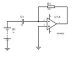
consider this simple circuitry. The distance between capacitor plates is varying. and I want to measure the varying current in the input side of op amp. Because of my circuit is providing very low current by this circuit I am converting it to volts. and after this I am getting this voltage o/p on CRO. My simple question is that will ordinary resistor is enough or should I use current sense resistor. MCP6022 is enough or should I use different IC. I don't know the current range. but my capacitor value is 10pf (now I am using different one for getting some significant results).

- - - Updated - - -

I see two problem ranges with your design:

- sensitivity limitations due to circuit noise (resistor and OP)
- crosstalk by capacitive coupling between see-saw ports, additionally crosstalk due to imperfect circuit layout

Noise can be calculated, the calculation will show if you need a better OP and/or a higher impedance feedback path.

Crosstalk can be reduced by static shields, it can be also cancelled by a compensation circuit or eleminated by running the measurement at different DC levels.

I show an ac source in my schematic because see sow structure vibrates on a particular frequency(10K). means I will get current at 10 K but I am getting it forever. whatever is my frequency I am getting o/p in response to i/p. I think it is due to cross talk. can you please tell me which kind of compensation circuit can eliminate this cross talk.
 

Hi,

10pF and 6kHz makes an impedance of 2.6 MOhms. with 1,5V it makes about 0.5uA.
This is a very small signal. Any influence will result in a large error.

Therefore
* either you use a high frequency signal. maybe 1MHz. It makes 16 kOhms. and a current of about 100uA
* or build an oscillator with your capacitor to change the frequency. (RC oscillator). Then measure the frequency and calculate the capacitance.

Klaus
 
Status
Not open for further replies.

Similar threads

Part and Inventory Search

Welcome to EDABoard.com

Sponsor

Back
Top