Continue to Site

Welcome to EDAboard.com

Welcome to our site! EDAboard.com is an international Electronics Discussion Forum focused on EDA software, circuits, schematics, books, theory, papers, asic, pld, 8051, DSP, Network, RF, Analog Design, PCB, Service Manuals... and a whole lot more! To participate you need to register. Registration is free. Click here to register now.

RDVV 5 WATTS MOUTOULOS

Status
Not open for further replies.
Hello.

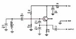
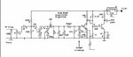
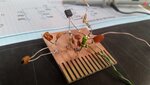
It looks mounted backwards because that is a J310 and there was another one before. What I will do is remove the plate from the chassis and analyze it thoroughly.
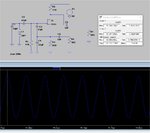
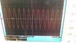
I clarify my disappointment: I have mounted Colpitts variable frequency oscillators with 6L6 valve and they worked instantly! :cry:

Thanks;)
 

Hi BigBoss !!!
I have a 200MHz bandwidth oscilloscope.

Oscillators are sensitive circuits and they can be easily disturbed by additional capacitance of the Scope probe. Therefore, in order to measure the health of the oscillator, you should use a coupling element-like a single turn coil- not to impact the oscillator.You will see-if oscillator really works- the signal on your scope.Oscillator functionality depends on many factors but the Load is one of them and most important.
Consequently using directly scope probe may halt the oscillator.
But first things first, you should be sure that the voltages and currents are OK.
 
Hello.

True, but I assure you that this ... It does not oscillate.
 

From the voltages on the latest posted schematic it looks to me as though the gate is connected to the 150ohm drain resistor. The source and drain are connected to the 47k and 680ohm, the could be either way round. Either that or the FET is dead. It should measure as a diode from source and drain to the gate.
I would expect around 3 volts across the 680ohm, but the wide spread on pinch off voltage means that it could be quite a bit different, and as Brian says the gate voltage could be a little negative, depending on how well it is oscillating and how much gate current there is. This is a common oscialltor so should work.
I did quick LTSpice simulation a Using a J310 the circuit should oscillate at around 100MHz with an inductor of about 82nH assuming 20pF for the tunig diodes, just a guess for the simulation and probably a bit high. Changing the FET will not make much differnce, I hust used that one for simulation as its part number was given on the layout.

Peter
 

Attachments

  • FET Osc.jpg
    FET Osc.jpg
    144.5 KB · Views: 107
Hi Peter!!
How good it feels to receive so much knowledge!

I have just printed your words to take them into account, I lean towards the dead transistor, apart from a thought that came to me: Even if I check the components before assembling them, it would not be strange if some of them were overlooked. I am thoroughly reviewing the components.
 

Again - putting the scope probe directly on the osc ckt may well stop it dead - when it is all fixed use a small coil on the scope probe to see if the osc is going - else it may well stop every time you touch the scope probe to the ckt ...
 
  • Like
Reactions: FvM

Hello everyone!!

It seems that Mr E. H. Colpitts does not like me ...
I have mounted the oscillator on an experimental board with new components, just like Peter did in LTSpice, and of course it didn't work for me. I don't have new J310s and I replaced it with an MPF112 (with another pin arrangement) and nothing! I modified the diagram to use a BF199 and there is no wobble either. I changed everything except the coil ... It occurs to me to measure its value and it measured close to 100nH, not too far from Peter's 82nH.

Could it be that Mr. Alzheimer is already knocking on my door? I'll not give up!
Happy Easter!
 

Attachments

  • Colpitts.jpg
    Colpitts.jpg
    34.2 KB · Views: 96
  • Coil.jpg
    Coil.jpg
    1.3 MB · Views: 97

Hi,

Experimental board and HF often is not a good combination.
Take a couple of photos and give some informations so we can see all the devices, the connections...and where supply and output is.

Klaus
 

Hi,

Right, so I will but it will be tomorrow, because in moments I will connect remotely to perform my work task. Just apologize for the delay.
The photos would be of the experimental plate?

Thanks!!!
Claudio
 

Proof it works! FET voltages measured with a DVM and with an 8.1V supply are: S= 1.48V, G= 0V, D= 7.6V.
The scope shows the output and measures the frequency as 114.3MHz. Note I used 20pf tuning capacitor as I didn't have a 22pF one to hand and a J304 FET although the type isn't critical.

Brian.

20210401_210110a.jpg
Scope.png
 

Hi Betwixt!!!

Great ... What is the clumsiness that I am doing? Question: The coil appears to be made with copper thicker than 0.5mm. What diameter of wire have you used?

Thank you
 

It was some copper stripped out of a power cable, probably slightly more than 0.5mm but that wouldn't stop it oscillating. For it to run, the gain has to exceed the component losses and the difference between wire diameters has virtually no effect on that. For interest I will replace the coil with one with the same number of turns but the thinnest wire I can find to see how much difference it makes.

The clue to what is wrong with your board is the DC voltages, there should be no path to put DC on the gate pin of the FET so it should measure zero volts. The DVM probably stops it oscillating or at least greatly de-tunes it but regardless no positive should be there. That only leaves two possibilities, the DC gets there through a short on the board -or- it gets there through a path inside the FET. If wired correctly, no current should flow from the drain pin (the only one that has a supply to it) to the gate but if the pins are swapped it will conduct and result in the voltages you see. It is possible that by wiring the FET incorrectly, it has been damaged, the gate in particular is very susceptible to excess current flowing.

Incidentally, there is an error in the original schematic but I'm not sure if it also exists on the board itself. There should be a capacitor (probably 100nF) from the output pin of the 9V regulator to ground.

Brian.

[update]
Coil replaced with the thinnest wire on hand (approx 0.2mm) . Still oscillates perfectly but the frequency dropped to 98MHz, probably because I had difficulty keeping the coil together, it wanted to unwind itself!

20210402_085953.jpg
 
Last edited:

According to the Spice simulation the Colpitts oscillator should work fine.
There is a situation when the oscillator starts to not oscillate, when the input impedance named "HF zur PLL" is below about 300 ohms. To fix this problem replace the 1nF coupling capacitor from the source of J310 with a 100pF capacitor.
On the other hand, you mentioned in one of the pictures that 8 turns (Cu 0.5mm) on 3mm has 1uH, which is not true. It has about 60nH, which is much less.
 

Attachments

  • Colpitts_JFET.jpg
    Colpitts_JFET.jpg
    231 KB · Views: 83

Hi there!

In a moment I'll get to work on the RDVV. Thank you for the amount of data provided. Vfone is absolutely right, I forgot to set the inductance meter to "zero", after doing it "L" measures 65nH in my case. I also accept the idea about damaged JFETs. I started by mounting the first in reverse and with the second J310 I don't know what happened. The new transistors I receive next week, now I will try a 2N5245, lower "gfs", but something would oscillate and reverse pins.

Thanks
 

I worked on the RDVV plate. I raised the 68pF capacitor, which according to the designer should be replaced by a 1nF one, in the air I installed the L coil and two 10pF + 15pF capacitors, since I did not have a 22pF capacitor. The voltage values on the transistor (2N5245 and j107, I tried both and they are new) are reflected in the graph. Sure ... It didn't work. The only thing I haven't replaced is the two 15pF capacitors. (¿?)

I think I will desist from continuing with the RDVV.

Thanks
 

Attachments

  • RDVV Modificated.jpg
    RDVV Modificated.jpg
    43.4 KB · Views: 85

Although the bias current is a bit low with these transistors, I'd ecpect that the circuit can still oscillate. Are you sure it doesn't? May be you are killing oscillations with your probing method.
 

I place the probe on the BFR91A transistor. I'll do a last test and replace both 15pF capacitors. I tested the PCB and it doesn't seem to have a problem. What's more, I just saw a video on Youtube with the identical RDVV board working properly, only it used an internal 1mm x 6mm Cu 4-turn "L" coil, a variant.
 

Decrease the Coupling Capacitor between the Tank Circuit and Oscillator Core.
I think 100pF is too high, it should normally be around 10p-22p. It loads the Tank Circuit thus Q Factor decreases.
 

Hi there!

In a moment I'll get to work on the RDVV. Thank you for the amount of data provided. Vfone is absolutely right, I forgot to set the inductance meter to "zero", after doing it "L" measures 65nH in my case. I also accept the idea about damaged JFETs. I started by mounting the first in reverse and with the second J310 I don't know what happened. The new transistors I receive next week, now I will try a 2N5245, lower "gfs", but something would oscillate and reverse pins.

Thanks
--- Updated ---

GOOD DAY!!!

As you saw it, I just checked it ... The oscillator works !! Of course. assembled on an external plate. I clarify that I use a JFET that I had in the semiconductor core: a 2N5245 with the original values and oscillates at 95.2 MHZ (low). I only got 22mV of RF. I made a change to it: I replaced the (source) 680R resistor with a 12uH inductor and the RF output increased to 185mV. What I observe is a very large instability, as you will see in the attachment, of continuous tension. This was before and after placing the inductor. I will mount the components on the RDVV PCB but am going to lift the coupling towards the BFR91A transistor to remove charges.

We will see....
 

Attachments

  • Oscilacion.jpg
    Oscilacion.jpg
    1.5 MB · Views: 85
  • Inestable.mp4
    1.9 MB
  • Placa.jpg
    Placa.jpg
    1.4 MB · Views: 83
Last edited:

Two inductors is a bad idea, go back to the 680 Ohm resistor!
I'm concerned about the low level you are seeing, I got 800mV p-p from the one I built here and with both the thin and 'fat' coil wire. If I read the scale on your first photograph as 100mV/div, you actually have about 500mV p-p. Check your scope is using a x10 probe and it is properly compensated or the readings will be highly inaccurate.

Brian.
 

Status
Not open for further replies.

Part and Inventory Search

Welcome to EDABoard.com

Sponsor

Back
Top