Continue to Site

Welcome to EDAboard.com

Welcome to our site! EDAboard.com is an international Electronics Discussion Forum focused on EDA software, circuits, schematics, books, theory, papers, asic, pld, 8051, DSP, Network, RF, Analog Design, PCB, Service Manuals... and a whole lot more! To participate you need to register. Registration is free. Click here to register now.

50 ohm 30GHz termination in microstrip ring coupler question

yefj

Advanced Member level 4
Joined
Sep 12, 2019
Messages
1,196
Helped
1
Reputation
2
Reaction score
3
Trophy points
38
Activity points
7,224
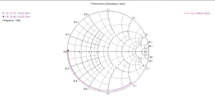
Hello,Shown below a ring quadrature coupler i have built.
However one critical problem is that from the diagram bellow i need the isolation port to be matched .
In theory i need to put 50Ohm termination to this port .
However i dont trust is 30GHz to put resistors because they can cause problems when i will solder them.
Is there a trick in transmission line theory that i can use to make a 50Ohm termination for my isolation?
Thanks.
1697879174836.png


1697879046280.png
 
In professional circuits, there is a thin film resistor to terminate this port. This resistor is trimmed by laser.
But I don't know you have a capability or not.
There is another option is to use Microstrip Microwave resistors that are pretty expensive. You have to supply almost perfect GND connection for that.
 
You are confusing resistor with transmission line impedance. A shorted 50 ohm line is a resonator, no absorbing termination. It's however possible to place the termination at a certain distance from the coupler with a 50 ohm line in-between.
 
Hello FVM, So you say as Big boss that thin film resistor is the only way and there is no transmission line trick to do such termination?
Thanks.
 
I think that you can terminate this port with a classical resistor+radial stub combination. Resistor is 0402 size, and radial stub is designed to make virtual ground (radius is less than quarterwave). It worked up to 26GHz in my case, and yours is only 4Ghz higher. I haven't used any special microwave resistors.
 
I think that you can terminate this port with a classical resistor+radial stub combination. Resistor is 0402 size, and radial stub is designed to make virtual ground (radius is less than quarterwave). It worked up to 26GHz in my case, and yours is only 4Ghz higher. I haven't used any special microwave resistors.
Hello Georgy, its a very interesting idea, i want to connect the logic.
virtual ground is a tern from OPAMPS where we we have plus on one side and minus on the other so in the middle we have 0V.
radial stub is shown bellow.
can i please have the physical intution regarging the transimssion line properties?
how exactly the do this effect?
Thanks.

1702621696283.png
 
Maybe better term is microwave short. We replace via to ground with a radial stub.
Ground via works both at DC and Microwave
Radial stub works only in some range of microwave frequencies, but have advantage of eliminating via inductance. Also you can bias radial stub to a voltage different than 0V (if there are no other connections from microstrip to ground).
2023-12-15 14 38 53.jpg
 
Hello , Is there some theory ragarding its properties?
so i would see short on the smith chart?
Thanks.

1702627324905.png

1702627302386.png
 
You can use radial stub or quarterwave stub.
Yes, there will be short on a Smith chart, and when you add 50 Ohm resistor in series it becomes a pretty good 50 Ohm termination.
1. For quarterwave stub it will behave like a 50 Ohm termination in narrow band.
2. For radial stub, it will behave like a 50 Ohm in a much wider band.
3. Even better bandwidth with "butterfly" radial stub (two radial stubs)
4. And the best I've seen is this: DOI:10.23919/EUMC.2018.8541403 A Novel Type of Broadband Radial Stub

Don't overthink it. You can simulate line terminated with resistor+radial stub. Just replace vias to ground with a single radial stub.

Added some examples from:
Ultralow-Power Six-Port Radar Realizing Highly Integrated Portable Radar Systems with Good Motion Sensitivity at Relatively Low Cost
A new compact V-band six-port receiver for high data-rate wireless applications. Check resistors on the right, relatively huge and it's 24GHz.
2023-12-15 16 40 05.jpg
 
Last edited:
Hello Georgy.Moshkin,basicly this stub needs to create a situation as shown below.
We send energy from port 3 to port 4 and nothing goes back as shown in S33.
I work with 35Ghz in microstrip of Er=2.94. so quarter wavelength is 1.39mm as shown bellow.
So the radius of the radial stub is 1.39mm .
the angle of the stub is 90 degrees.
but when i look at the S param(in the photos signs as STUB) ,all the energy which when from port 3 goes back to port 3.
Only when i added the 50Ohm element i got to the desired effect.
Could you please help me understand why stub alone is not enough ?
Why we need to add 50Ohm? with transmission line theory explanantion?
Thanks.


1702671433900.png

1702671021678.png

1702671202906.png

1702671144894.png


1702670242419.png


1702669487534.png
 

Attachments

  • 1702671125675.png
    1702671125675.png
    49.7 KB · Views: 33
Is there a resistor? I see a small rectangle near radial stub, not sure if it's defined as lumped element. If it's not there, then add a resistor.

Also, you need to reduce radial stub radius to something around 0.9-1.1mm You can find best radius from simulation, or use some analytical formula for radial stub radius.
Btw, for butterfly radial stubs radius of each individual stub would be even smaller.

You can search this forum for "end effect" for patch antennas and stubs: actual lengths are smaller than half wavelength for antenna, and smaller than quarterwave for quarterwave stubs. The thicker your substrate is, the shorter physical length is due to "end effect".

To sum up, ensure that there is a resistor and tune stub radius, so it's a little smaller than a quarterwave.
 
Only when i added the 50Ohm element i got to the desired effect.
Could you please help me understand why stub alone is not enough ?
Why we need to add 50Ohm? with transmission line theory explanantion?
Seriously? You are still behind the idea of using a transmission line as resistor? Look at Smith chart. Input impedance of transmission line is located on the circle (purely reactive), 50 ohm resistance in the center.
 
Hello Georgy , i got to -26dB isolation.
my system is 50ohm descrete component and the radial stub as you advised.
What the the Transmission line logic of connecting in series 50Ohm resistor to radial stub for issolation.
I would like to know the smith chart logic of how exactly 50 ohm in series with quarter wave stub gets us to the unity area ash shown below?
1702731952300.png


1702731583429.png


1702731513655.png
 
What the the Transmission line logic of connecting in series 50Ohm resistor to radial stub for issolation.
How do you ever want to design RF circuits with no understanding of RF components and RF concepts?

You wanted a 50 Ohm to ground. Georgy showed you that you can use the radial stub to create an RF short, instead of using a via. That's it.
 
Hello Volker,Yes i succseeded in building such isolation stub,i published the simulation results above.
You are correct i am weak on the transmission line logic .
I want to learn how exactly 50 Ohm in series witl quarter wave stub got me to the center of the smith chart.
If you have some manual?
Thanks.
 
I want to learn how exactly 50 Ohm in series witl quarter wave stub got me to the center of the smith chart.
But it was explained again and again?

The radial stub gives an RF short at your operating frequency, and you connect one end of the 50 Ohm resistor to that RF short.
I hope you don't ask now why 50 Ohm termination gets you to the center of the Smith chart ...
 
Have a look here to learn more about resistor response at microwave frequencies:

Many 0201 types should be fine, I can't recommend a specific type. The type that you linked with 0.5% tolerances might be ok, but the RF performance (laser trimming style, see PDF) is certainly more important that the specified tolerance (that applies to DC resistance!)

Here is a data sheet for a resistor series trimmed for good RF performance (low parasitics in laser trimming), note the "flip chip" comment.

0201_50.png
 

LaTeX Commands Quick-Menu:

Part and Inventory Search

Welcome to EDABoard.com

Sponsor

Back
Top