Continue to Site

Welcome to EDAboard.com

Welcome to our site! EDAboard.com is an international Electronics Discussion Forum focused on EDA software, circuits, schematics, books, theory, papers, asic, pld, 8051, DSP, Network, RF, Analog Design, PCB, Service Manuals... and a whole lot more! To participate you need to register. Registration is free. Click here to register now.

RC circuit added to MCLR pin of PIC18F26K20

Status
Not open for further replies.
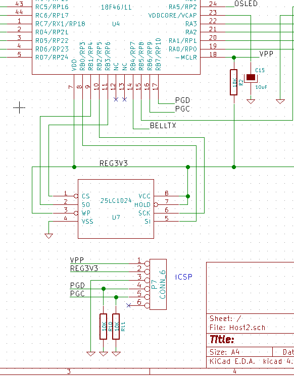
Data sheet page 369:
2: Voltage spikes below VSS at the MCLR/V PP/RE3 pin, inducing currents greater than 80 mA, may cause
latch-up. Thus, a series resistor of 50-100 should be used when applying a “low” level to the
MCLR/VPP/RE3 pin, rather than pulling this pin directly to VSS.
nothing there about needing a series resistor between programming voltage and VPP. The VPP pin should have a pull-up resistor to VDD for normal operation but the current through it is only normal CMOS input leakage of a few nA at most.

The only other reference to a series resistor mentions 1K but is specific to instances where MCLR is external and the supply rise time is long. It's purpose there is to prevent excess current from the C in the RC delay from discharging rapidly into the pin if VDD drops rapidly.

100 Ohms in series with VPP probably won't stop it programming but note the current to the pin during a programming cycle can be as much as 10mA.

Brian.
 

Yes, that has been already mentioned in the datasheet (it is actually a monster document) but with the capacitor it also helps a bit in pulse shaping.
Ok thanks, and it sounds like you are speaking of like in picture B of post #12 above, not how i originally thought you meant.
 

Believe me, all you need is one resistor between RB5 and VDD, no capacitor and no series resistors. You can use 4.7K if you want but during the programming cycle VPP is raised to 9V so you waste almost 2mA for no reason at all. The resistor is just there to prevent RB5 from floating and with internal MCLR enabled it behaves like any other digital IO pin and draws negligible current so you can make the resistor a higher value quite safely.

Brian.
 

Thankyou Betwixt, i am taking your post #23 as the way to do it when the MCLR function is not enabled. (in other words when the MCLR pin is a digital input, RE3)
 

This is an extract from one of my designs to demonstrate:

The MCU is an 18F46J11 which is not much different electrically to yours.

Incidentally, I made a modification to the ICSP wiring later and used a 9-pin 'D' socket instead. This project has parameters that need updating occasionally so by carefully choosing pins I made the 'D' work as both a programming socket and an RS232 serial link without risk of either function damaging the other.

Brian.
 
  • Like
Reactions: treez

    T

    Points: 2
    Helpful Answer Positive Rating
Thankyou very much indeed Betwixt, today i had some simple test code running with MCLR defined initially as external reset and nothing connected to MCLR...it wouldnt work properly.....so i connected it the way you suggested, with the 10k to Vdd...and i changed it to disable the external reset, and it worked right as rain! Thankyou very much.

This is a big step in getting our actual code working. Today we unfortunately found that our remote software engineer had defined two unused micro pins as inputs......they had blind tracks extending from them to the programming vias. We will ask him to correct tomorrow. Hopefully this was a big cause of our problems there.
 

Status
Not open for further replies.

Similar threads

Part and Inventory Search

Welcome to EDABoard.com

Sponsor

Back
Top