samruddhathakur
Junior Member level 3
Hi,
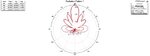
I have designed and simulated a microstrip Patch Antenna Array (4x4) in HFSS but the radiation pattern achieved is not symmetrical. Can any one tell me how to achieve symmetrical pattern.
The spacing between all the Patches is contant 0.8 times wavelength.. I am ataching the image
I have designed and simulated a microstrip Patch Antenna Array (4x4) in HFSS but the radiation pattern achieved is not symmetrical. Can any one tell me how to achieve symmetrical pattern.
The spacing between all the Patches is contant 0.8 times wavelength.. I am ataching the image