Continue to Site

Welcome to EDAboard.com

Welcome to our site! EDAboard.com is an international Electronics Discussion Forum focused on EDA software, circuits, schematics, books, theory, papers, asic, pld, 8051, DSP, Network, RF, Analog Design, PCB, Service Manuals... and a whole lot more! To participate you need to register. Registration is free. Click here to register now.

Radar antenna feeding question( with photo)

Status
Not open for further replies.

bkd

Full Member level 2
Joined
Dec 18, 2005
Messages
120
Helped
3
Reputation
6
Reaction score
2
Trophy points
1,298
Activity points
2,105
radar p-18 antenna

HI
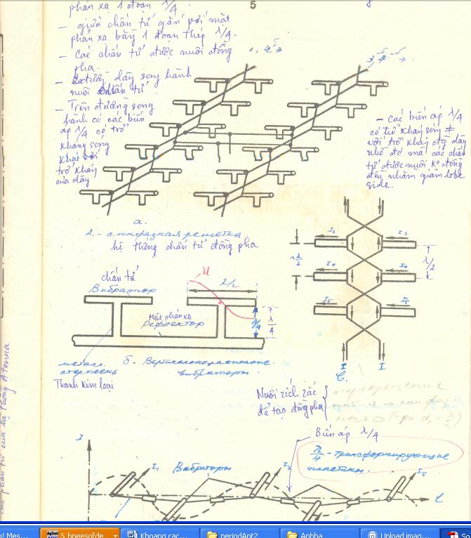
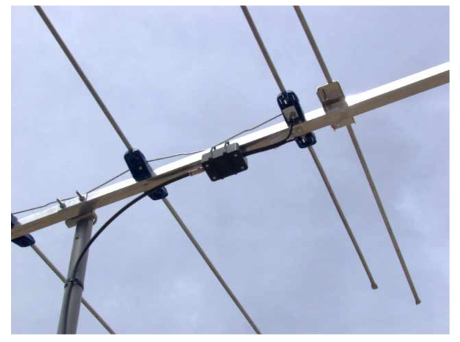
I have this photo but I do not have any ideas about how the feeding system works. So If anyone have experience in this field please help me out.
**broken link removed**
 

russian radars antenna theory

I am not quite sure but i think it might be some of the following examples:

a) Parabolic cylinder antenna (equidistant dipole feeds)
b) Equidistant antenna array (consist of dipoles)
 

I think they are equal in feeding for each dipole, but I need more detail about the feed. Anyway thank you so much for your reply
 

You are looking at an array antenna. The elements are probably dipoles over a graoud plane to make them somewhat directive and are probably fed in phase to produce a broad side beam.

Kraus and Silver are places to start for more information.
 

I checked, and i think i known what is it.

It is antenna for IFF (secondary radar) for Russian radar P - 18.
So as already said, it is array of dipoles.

I will try to find more and post it here.
 

I have just found it, but if anyone have mo detail please post it here


Added after 2 hours 48 minutes:

I also confirm that it is P18 of Russia. SO ND, are you from Russia or VietNam ?. I think you are an expert in radar. If you find any detail please post for me.
 

Well, i' m nor from Russia, nor from Vietnam. And i don't think i am expert, but i hope i' ll will be.
Anyway i didn' t have time to check it today. And i can not promise that i' ll have time to find data quickly, but i am pretty sure that i can find technical data you are looking for.

Best regards.
Dejan
 

Hi bkd,
Azulykit seems to be right. It looks like a dipole array above a ground plane. the interesting thing about the design is that the dipoles are actually one solid "T" which you can do if the separation from the ground plane is quarter of the operation wavelength. This turns the middle of the dipole to be in open circuit in comparison to the ground plane. It also increases the gain since each dipole has a reflection which is half a wavelength away "behind the ground plane" with opposite phase, thus they interfere constructively.
The feed for the entire array is in series, in contrast to the regular "corporate" feed of an array, I assume in order to simplify the feed network design and to save on splitters.
The series feed probably also causes some amplitude taper as well unless there is some other mechanism to compensate for it, thus you'll have a bit different radiation pattern than the regular sinc^2 array pattern.
The basic for antenna arrays are in every antenna book. A thorough one which definitely have examples of dipole above ground plane is Balanis: "Antenna Theory: Analysis and Design". The Kraus book is also good.
Hope this is helpful.
Ori
 

Thank ND, azulykit and orisapir. Now the problem is how to calculate the impedance of ceisscross feeding. For the parallel twin lead wire the characteristic impedance seems 300 ohm, but the impedance of this lamda/2 dipole is 73 ohm ?? ANd they have parallel 10 dipole seperate lamda/2 in distance. So I wonder here is how to matching the impedance. ANd from the port how can I set the impedance of the port in simulation program
 

Hi bkd,
Note that the dipoles are fed at their end, which means, that the input impedance is much higher. You probably need to simulate to find out a close value for the input impedance.
 

I have found down this one . The coxial cable( 75 ohm) connect with balun ( 1:4) and then connect with 300 ohm twin-lead wire line, meaning that the input impedance of the antenna is 300 ohm at operating frequency. So anyone know the input impedance of the dipole here, the input impedance of the criss cross line and how they matching them .
The input impedance of the twin lead wire line is using Z=120/sqrt(epslon)*ln(2S/d)
S is distance between two wire, d is the diameter of wire
I wonder if the input impedance of the crisscross are the same ??
 

Status
Not open for further replies.

Part and Inventory Search

Welcome to EDABoard.com

Sponsor

Back
Top