Continue to Site

Welcome to EDAboard.com

Welcome to our site! EDAboard.com is an international Electronics Discussion Forum focused on EDA software, circuits, schematics, books, theory, papers, asic, pld, 8051, DSP, Network, RF, Analog Design, PCB, Service Manuals... and a whole lot more! To participate you need to register. Registration is free. Click here to register now.

[SOLVED] RA0 and RA1 not working properly when used at a time

Status
Not open for further replies.

Waqas_MicroSolutions

Member level 1
Joined
Oct 23, 2010
Messages
37
Helped
2
Reputation
4
Reaction score
2
Trophy points
1,288
Activity points
1,538
Hi there,
I have configured RA0 and RA1 in PIC16F676 as output. They work well when used individually.
When both are set/Cleared one after other, they doesn't work. If one pin is turned on, other is turned off by it self(This is not required). While same code works well on other pins in PORTA! I am using high band gap, and turned off MCLRE, WDT, BODEN,PWRTE and using internal RC oscillator with OSCCAL=0x34FC (Max Freq).
Here is my code, compiler is MikroC:
Code:
#define BUZZER PORTA.F1
#define BLOW PORTA.F0
void main (){
   ANSEL=0x60;
   TRISA.F0=0;TRISA.F1=0;
   while(1){
      BLOW=0;
      Delay_ms(500);
      BUZZER=0;
      Delay_ms(500);
      BUZZER=1;
      Delay_ms(1000);
      BLOW=1;
      Delay_ms(1000);
   }/*while*/
}/*main*/
Result can be observed in Proteus..
Please help!
 

In general, when modifying output bits of a port you should use LATA not PORTA. Have a search for ' read-modify-write' issues on PICs.

Keith
 

In general, when modifying output bits of a port you should use LATA not PORTA. Have a search for ' read-modify-write' issues on PICs.
Keith
why not for other PORT PINs in PORTA???
LATA, is undefined Identifier in MikroC, neither it is present in PIC16f676's datasheet!

---------- Post added at 23:12 ---------- Previous post was at 22:52 ----------

How to fix PIC microcontroller read modify write bugs - YouTube
I have seen this descriptive video, and I have already took care of RMW in my code above, so there is no question of RMW error as time delay is large enough....
RA0 and RA1 are also multiplexed with comparator inputs, so is there anything to do with that ???
 

LAT registers are only present in the high end PIC18+ devices and the latest 16F.

You don't need to set the TRIS registers inside the program loop but that shouldn't stop it working.
Is it possible the devices connected to the port pins are causing the trouble? Are BUZZER and BLOW inductive devices or do they draw excesive current?
Check the ANSEL value is correct and the .Fx pin description, I don't use MikroC, that's just a guess at the problem.

Brian.
 

LAT registers are only present in the high end PIC18+ devices and the latest 16F.

My mistake. I have used all sorts of PICs, 12, 16, 18 and 24 and I seem to remember they all had LAT registers.

Keith
 

I have configured RA0 and RA1 in PIC16F676 as output. They work well when used individually.
When both are set/Cleared one after other, they doesn't work. If one pin is turned on, other is turned off by it self(This is not required). While same code works well on other pins in PORTA! I am using high band gap, and turned off MCLRE, WDT, BODEN,PWRTE and using internal RC oscillator with OSCCAL=0x34FC (Max Freq).

As Brian mentioned, the issue could be excessive current sourced from RA0 and RA1, or excessive current sourced from PORTA and PORTC combined, which have a source limit of 25mA and 200mA respectfully.

Reference: PIC16F630/676 Datasheet, Section: 12.0 ELECTRICAL SPECIFICATIONS, pg 85

12.0 ELECTRICAL SPECIFICATIONS
Absolute Maximum Ratings†
Ambient temperature under bias.......................................................................................................... -40 to +125°C
Storage temperature ....................................................................................................................... -65°C to +150°C
Voltage on VDD with respect to VSS .................................................................................................. -0.3 to +6.5V
Voltage on MCLR with respect to Vss .................................................................................................. -0.3 to +13.5V
Voltage on all other pins with respect to VSS ....................................................................................... -0.3V to (VDD + 0.3V)
Total power dissipation(1) ................................................................................................................. 800 mW
Maximum current out of VSS pin ......................................................................................................... 300 mA
Maximum current into VDD pin ............................................................................................................ 250 mA
Input clamp current, IIK (VI < 0 or VI > VDD)......................................................................................... 20 mA
Output clamp current, IOK (Vo < 0 or Vo >VDD)...................................................................................... 20 mA
Maximum output current sunk by any I/O pin.......................................................................................... 25 mA
Maximum output current sourced by any I/O pin ..................................................................................... 25 mA
Maximum current sunk by PORTA and PORTC (combined) .......................................................................... 200 mA
Maximum current sourced PORTA and PORTC (combined) .......................................................................... 200 mA

Can you post the datasheet of both the BLOW and BUZZER devices?

Also as Brian mentioned if the devices are inductive or highly capacitive, an alternative method of driving them maybe required.

After reviewing your code it appears the analog comparator module has not been disable which is required for Digital I/O on pins RA<2:0>.

There is a misprint in the datasheet's example, so refer to the errata.

Reference: PIC16F630/676 Rev. A Silicon/Data Sheet Errata, Section: 5. Module: PORTA: Initializing Example, pg 6

5. Module: PORTA: Initializing Example

Change Example 3-1: Initializing PORTA to the following (bold text):

EXAMPLE 3-1: INITIALIZING PORTA
BCF STATUS,RP0 ;Bank 0
CLRF PORTA ;Init PORTA
MOVLW 07h ;Set RA<2:0> to
MOVWF CMCON ;digital I/O

BSF STATUS,RP0 ;Bank 1
CLRF ANSEL ;digital I/O
MOVLW 0Ch ;Set RA<3:2> as inputs
MOVWF TRISA ;and set RA<5:4,1:0>
;as outputs
BCF STATUS,RP0 ;Bank 0

I would recommend trying the following code:

Code:
#define BUZZER PORTA.F1
#define BLOW PORTA.F0
void main ()
{
   CMCON=0x07;    
   ANSEL=0x00;
   TRISA.F0=0;
   TRISA.F1=0;

   while(1){

      BLOW=0;
      Delay_ms(500);
      BUZZER=0;
      Delay_ms(500);
      BUZZER=1;
      Delay_ms(1000);
      BLOW=1;
      Delay_ms(1000);

   }/*while*/
}/*main*/

Also make sure you enter the correct system clock frequency generated by the internal oscillator into the "Project Settings" of MikroC. Without the proper system clock frequency, the generated delays from Delay_ms() routine will be incorrect.

BigDog
 

As Brian mentioned, the issue could be excessive current sourced from RA0 and RA1, or excessive current sourced from PORTA and PORTC combined, which have a source limit of 25mA and 200mA respectfully.

Can you post the datasheet of both the BLOW and BUZZER devices?


BigDog
BLOW is simply an LED(Battery Low), and BUZZER is a12V Buzzer which is being drived with BC547....

CMCON=0x07;
ANSEL=0x00;
BigDog
I tried this and some other things before posting my question on edaboard.....
I used 6 different ICs the result is the same in proteus as well...
While trying these things I have learned many valueable things but I have not yet found any solution for this one ..
 

Try disconnecting the output loads and monitor the signals will an oscilloscope or multimeter. You haven't described your loads fully, but either could be excessively loading the ports depending on component values.

Keith
 

The problem, it seems to me, is the comparator. However, you said that it still doesn't work. If BLOW is an LED (and you limited current properly with a resistor) and BUZZER is connected to a transistor (and you limited current to the base), there can't be an over-current issue.

I've used this code:
Code:
#define BUZZER PORTA.B1
#define BLOW PORTA.B0

void main (){
   ANSEL=0x60;
   TRISA.B0=0;TRISA.B1=0;
   CMCON = 7;
   while(1){
      BLOW=0;
      Delay_ms(500);
      BUZZER=0;
      Delay_ms(500);
      BUZZER=1;
      Delay_ms(1000);
      BLOW=1;
      Delay_ms(1000);
   }/*while*/
}/*main*/

and it simulated perfectly fine.

Try it again and let us know. What you also can do is, upload the hex file so we can test it. And also the project file and the DSN (simulation) file.

Hope this helps.
Tahmid.

---------- Post added at 14:33 ---------- Previous post was at 14:32 ----------

While .Fx should not cause a problem (and it didn't when simulating), I personally use .Bx (and this doesn't show the red underline in mikroC as shown by .Fx).
 

Code:
#define BUZZER PORTA.B1
#define BLOW PORTA.B0

void main (){
   ANSEL=0x60;
   TRISA.B0=0;TRISA.B1=0;
   CMCON = 7;
   while(1){
      BLOW=0;
      Delay_ms(500);
      BUZZER=0;
      Delay_ms(500);
      BUZZER=1;
      Delay_ms(1000);
      BLOW=1;
      Delay_ms(1000);
   }/*while*/
}/*main*/
[/QUOTE]

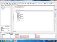
I'm using MikroC 8.2.0.0,
here is the result....
 

Status
Not open for further replies.

Part and Inventory Search

Welcome to EDABoard.com

Sponsor

Back
Top