Continue to Site

Welcome to EDAboard.com

Welcome to our site! EDAboard.com is an international Electronics Discussion Forum focused on EDA software, circuits, schematics, books, theory, papers, asic, pld, 8051, DSP, Network, RF, Analog Design, PCB, Service Manuals... and a whole lot more! To participate you need to register. Registration is free. Click here to register now.

R1 heating in opto back indication

Status
Not open for further replies.

haseeb123

Newbie level 6
Joined
Jun 7, 2011
Messages
14
Helped
0
Reputation
0
Reaction score
0
Trophy points
1,281
Activity points
1,416
Hello

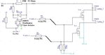
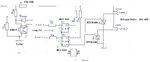
I have a problem with my circuit as enclosed. R1 (25 W / 15 Ohms) is heating up too much. I intend to get back indication that
my lamps 1 and 2 have failed. Where it says (LP_Fail To PIC), thats the pin that is pulled HIGH when the optocoupler shuts off in the
event of a lamp failure. I'm using 24VDC. The problem is not programming nor the PIC, but is infact optocoupler back indication
that I want and it seems that there is a flaw in the circuit. R1 over heats too much too quickly. My lamps each draw 1amp current @
24VDC. If I by pass the optocoupler and R1 and connect the 24VDC directly, then i have no issues and the lamps work great with no
over heat issues. I have tried high/low values of R1 and with higher watts as well but the heating up of R1 is far to great and u can smell it burning! Please can someone suggest a fix to the over heating problem or suggest another slicker way of back indication to the
PIC in the event of my lamp failures.

Haseeb
 

Attachments

  • circuit.JPG
    circuit.JPG
    28.8 KB · Views: 106

I don't believe, that the current sense resistor has 15 ohm. But to put in a reasonable low voltage drop sense resistor, you need a more sensitive current detector. There are many possible solutions, don't know what's appropriate for you:
- using a high side current sense IC
- using an OP differential amplifier
- using two PNP transistors in a current mirror configuration.
 

Thank you so much!

I never thought of it that way....and you explained very well and it makes perfect sense.

I will try what you say and if any problem will get back to you.

Once again, thank you very much

Haseeb
 

Hi


I have just successfully solved the problem. I had to feed in the circuit 18V DC instead of 24VDC and I also changed the resistor to 3R0 / 25W and this solved the heating problem successfully.


Now I have the same R1 over heating problem but this is now for a 24V AC version circuit board. I'm

powering two halogen light bulbs at 24V 50W each. Thats about 2Amps per lamp. The circuit diagram

is enclosed. I have tried feedng in 18V AC and changing R1 to 1R0 25W but still the over heating of R1 is taking place.


Please can someone look at my circuit diagram (enclosed) and suggest what might be wrong and

why is R1 heating up too quickly and too hot??


Thanks

Haseeb
 

Attachments

  • 24VAC.JPG
    24VAC.JPG
    35.4 KB · Views: 100

You have to understand that the power on the resistor will be P = I² * R so for
1 ohm and 4A you have 4²*1=16W
4 ohm and 4A you have 4²*4=64W

on the other hand the current will be lower because the 12v/100w bulbs (combined) will have a resistance of 1.44 ohm so depending on the R1 value you will have a significant voltage drop and almost half the current than the 4A.

Use a low resistor 0.1 ohm or even less will be better and use a differential amplifier to amplify the voltage you get from R1.
If you move R1 in the lower side (at the gnd side of the control devices) it would be easier to connect the opamp or else you have to use an additional divider.

DiffAmp.jpg

Alex
 

Hey Thanks for the tip.

I appreciate it. :grin:

regards
Haseeb
 

Perhaps you solved the problem, but you may like to look at this solution (attached):

Edited:
HiCurrSns_01.png is for DC supply
 

Attachments

  • HiCurrSns_01.png
    HiCurrSns_01.png
    101.3 KB · Views: 100

Thank you very much
I will look in to this new design.

Warm Regards
Haseeb
 

For AC, I designed this ...

Edited:
If you can get high current diodes you can add two in parallel (and opposite) to Rsns. You may need to lower the value of Ri (now it is 220 Ohms). These two diodes will reduce the heat dissipation since the AC voltage at Rsns will be limited by the forward voltage of each diode. Pdis (approx.) = 1* Irms * 0.9

Edited:
The value Rsns with diodes needs to be increased (say to 2.2 Ohm or even removed) to leave most of the load current to pass in the diodes. Ri value depends on the average difference between the forward voltage of the power diode and of the IR LED (in the optoisolator). Ri in this case could be as low as 10 Ohms.

As FvM has pointed out, this similar solution of yours is far from being the best one due to the relatively high heat dissipation in sensing the current.
 

Attachments

  • HiCurrSns_02.png
    HiCurrSns_02.png
    121 KB · Views: 104
Last edited:

Your suggestions are continuing the disadvantage of the original design which has been an unreasonable high voltage drop. The specification is to detect 1 A reliably and carry up to 2 A. So the BJT transistor variant will have up to about 3 W power dissipation and the optocoupler variant 6 W. You'll see, why we would want to use a shunt with lower voltage drop and a more sensitive voltage detector. Besides the suggested solutions, dedicated high side sense IC or standard differential amplifier, there are some more options, e.g. two pnp transistors in a current mirror configuration. The voltage drop causes a current mirror imbalance and respective output current.
 
  • Like
Reactions: KerimF

    KerimF

    Points: 2
    Helpful Answer Positive Rating
A solution like this is shown here **broken link removed**

Alex
 

You are right FvM.
But don't you think if all of us work hard to give the best solution (in the world) then only one of us would need to answer.
On the other hand, I believe the askers are as smart as we are all so he/she will likely choose the best convenient answer for his/her situation after reading all messages (circuits, comments and remarks).

In my case, since I cannot find and buy easily MCUs with ADC and also be able to write their assembly programs using the simple tools I have, I just use the timer interrupt to measure the charging time of a capacitor which could reflect what I need to measure... Getting something is always better than having nothing. :smile: So I understand if some others may not be interested in every best solution. :wink:

---------- Post added at 21:41 ---------- Previous post was at 21:11 ----------

Thank you very much
I will look in to this new design.

Warm Regards
Haseeb

As suggested for the AC circuit, we can decrease the dissipation on Rsns (DC version) by adding a power diode but this will need also to split Rsns to two resistors. If you are interested, I will redraw it again (with diode).

Kerim
 
  • Like
Reactions: FvM

    FvM

    Points: 2
    Helpful Answer Positive Rating
Hi Kerim

thanks for the offer and help.

Yes I would certainly be interested in a redraw diagram from you with regards to the diode version as you have said in your last post.

Please can you post it here.

Im still open to options and trying out various tricks to get the heat dissipation down.

Im still working on it and will update you with the results.

thanks
haseeb
 

Sorry, but are you sure you can't follow what was suggested by FvM (post #11) by using the IC (or an equivalent one) to which Alex referred (post #12) ?

Even by adding diodes, the disspiation will not be low enough though lower than using a resistor.

In case you have no choice but to add a diode (if DC) and 2 diodes (parallel and opposite if AC) in series between the supply output and your lamp(s), could you check first that the heat dissipation of your available power diode(s) (replacing the current sensing resistor) is acceptable? And perhaps you can also measure the diode forward voltage by a simple voltmeter in the least:
For DC: by measuring its average DC value since you may not be able to see its ripple.
For AC: meausre the AC value though the meter will assume the measured signal as being sinusoidal (and not quasi trapezoidal).

Kerim
 
Last edited:

Ok Kerim

Thanks for the update and further suggestions.

Let me measure my findings and I will get back to you.

Warm Regards
Haseeb
 

Status
Not open for further replies.

Similar threads

Part and Inventory Search

Welcome to EDABoard.com

Sponsor

Back
Top