Continue to Site

Welcome to EDAboard.com

Welcome to our site! EDAboard.com is an international Electronics Discussion Forum focused on EDA software, circuits, schematics, books, theory, papers, asic, pld, 8051, DSP, Network, RF, Analog Design, PCB, Service Manuals... and a whole lot more! To participate you need to register. Registration is free. Click here to register now.

Questions on selecting components for buck circuit

Status
Not open for further replies.
Re: Buck circuit questions.

I spent some time this morning pondering how to power this IC (as opposed to looking for another one) when suddenly I remembered reading somewhere that you can build a voltage divider instead of using the 19-26kohm PoE sensing resistor. I've attached my new schematic to show how I thought that would work. I also renumbered the components.

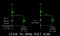
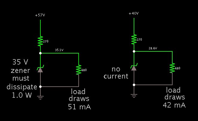
The customary arrangement for zener regulation is below. In parallel with the load. Resistor low enough to carry enough mA to the IC.

Supply level on the IC will still vary. The series resistor must be rated for more than 1 watt. These are safeguards to get proper operation, for all PoE supply volt levels. It depends on what range of supply the IC likes.


Your zener diode is in series with the IC supply pin. The IC gets power through a 12k resistor (R1). The most it will get is 4 mA. There's only a remote chance that's enough.

One part I am worried about with this configuration is that the controller's transistors max current rating is only 100mA. But later in the datasheet it says "Each transistor has antisaturation circuitry that limits the current through that transistor to a maximum of 100 mA for fast response." So, I'm not sure if I'm allowed to exceed that or not. I used the voltage divider calculator at hyperphysics to determine the power available at the IC and divided by the voltage to get the current which seems to be at acceptable levels.

This must apply to the internal transistor. I do not believe the IC is able to govern an external transistor.

I've seen datasheets which show one example with an external mosfet/transistor, and another without. It's possible you can get either to work with your IC.

If you can use an external switching mosfet, the 100 mA restriction probably won't apply.

A free simulator called LTspice is frequently recommended by posters here. It may contain switching controller IC's which you can try.
 
  • Like
Reactions: thepaan

    thepaan

    Points: 2
    Helpful Answer Positive Rating
Re: Buck circuit questions.

BradtheRad,

I'm not sure I understand what is going with the zener diode in your picture. My intent of using one is to prevent the device from turning on during the classification stage of PoE which would give it a classification of 0. The only way to do that is to connect it to a switch to control the main loop, or to put it in series with the IC Vin. I do get what you are saying about the resistors being too high though. What do you think about this setup where the 300ohm resistor represents the IC?

The current limit is on the internal transistor, although the external FET in my previous drawing did have a gate max voltage of 30. The problem then is getting the voltage low but keeping the current just right. I think the way I split it int he link above would work.

I installed LTspice, but I'm at a loss on how to get the regulator in there. Should I just pick one from Linear that is as close as I can find, or is there some place to download the IC into the program?
 

Re: Buck circuit questions.

I'm not sure I understand what is going with the zener diode in your picture. My intent of using one is to prevent the device from turning on during the classification stage of PoE which would give it a classification of 0. The only way to do that is to connect it to a switch to control the main loop, or to put it in series with the IC Vin.

This is an area where you'll need to see how well it works. Does the IC have a built-in time delay? Does it check conditions at all pins before it starts producing pulses?

A series zener by itself is not likely to add a time delay. What it will do is conduct when incoming PoE is high enough to overcome its threshold. Below that it will not conduct. Thus if PoE rises slowly, the classification stage might occur while your IC is off. It may result in doing what you want.

If you need a longer delay, however, then you may need to put a capacitor in there somewhere. Or add another circuit to provide power after a delay.

As for my post #21, it shows typical use of a zener to limit supply V.

Since the IC must not receive greater than 40V supply, I reckon 35V regulation is adquate. My two schematics show what happens when incoming PoE is highest (57V) and lowest (40V).

It may require that you find out what supply V works with your IC, to find out which is the best way to configure the zener.

I do get what you are saying about the resistors being too high though. What do you think about ['URL='this setup] where the 300ohm resistor represents the IC?

It may work. The zener subtracts 27V.

Then notice that with the 270 ohm resistor you are automatically dividing voltage by 2 (approx). So the supply might range from 7V to 16V.

Question: Can you be certain it produce sufficient voltage to drive the mosfet?

The current limit is on the internal transistor, although the external FET in my previous drawing did have a gate max voltage of 30. The problem then is getting the voltage low but keeping the current just right. I think the way I split it int he link above would work.

Yes, these considerations are all important to getting proper performance. Some adjustments will happen automatically, of course.

One factor that may become crucial, is whether you can count on 350 mA always being available from PoE. Therefore it may be wise to minimize the instantaneous current you draw from the PoE.

Better a longer On-time at less current, than shorter On-time at more current.

To optimize this, the transformer ratio may need to be 1:5, or 1:10, or a value in between.

It would be great if you could purchase a few different ratios, and use the transformer that works best. A simulator can help, but its results are only tentative.

I have been adjusting your latest simulation, making a priority to draw minimal current, yet power the load even when PoE supply is 40V.

I find the transformer ratio should be 1:8, 11 mH primary winding, driven at 11 kHz, and 56 percent duty cycle. Again this is only theoretical.

The 1:8 ratio of course calculates to step down 40 V to 5 V. However when PoE is at 57V, the duty cycle must be reduced.

The transistor is driven to saturation. A mosfet can be done likewise.

https://tinyurl.com/9fwuqqv

I installed LTspice, but I'm at a loss on how to get the regulator in there. Should I just pick one from Linear that is as close as I can find, or is there some place to download the IC into the program?

I haven't used LTspice enough to know for sure, but I've heard of cases where someone makes a data file so a simulator can run this or that component.
 
  • Like
Reactions: thepaan

    thepaan

    Points: 2
    Helpful Answer Positive Rating
Re: Buck circuit questions.

PoE seems very controlled, as far as I can tell. **broken link removed** has a good chart on page 3. The classification stage does not recieve more than about 20V, so anything over this should be fine. To be compliant with the specification though, my device should turn off if it recieves less than 30V.

Apparently my understanding of Zener diodes was incorrect. I was under the assumption that the voltage drop across the diode was about .7 in reverse, as it is forward on standard diodes. The IC needs at least 8V on Vin and that looks like more than enough for the FET gate as well. The voltage after a 27V zener should not exceed 30V, so all that is left is to limit the current. If I'm doing this right, using ohms law I should need at least a 340 ohm resistor to bring it down to 50mA at 44V, but the zener would need to be rated for over ~1.5W. :(
 

Re: Buck circuit questions.

PoE seems very controlled, as far as I can tell. **broken link removed** has a good chart on page 3. The classification stage does not recieve more than about 20V, so anything over this should be fine. To be compliant with the specification though, my device should turn off if it recieves less than 30V.

It appears that your device will be evaluated about 550 mSec after startup. Its current draw will be examined during the 75 mSec window.

Therefore you have to make sure it is drawing its operating range of amperage before that time, so it can receive classification.

Apparently my understanding of Zener diodes was incorrect. I was under the assumption that the voltage drop across the diode was about .7 in reverse, as it is forward on standard diodes. The IC needs at least 8V on Vin and that looks like more than enough for the FET gate as well. The voltage after a 27V zener should not exceed 30V, so all that is left is to limit the current. If I'm doing this right, using ohms law I should need at least a 340 ohm resistor to bring it down to 50mA at 44V, but the zener would need to be rated for over ~1.5W. :(

This is a case where using resistive drop is workable. Notice that the controller IC may draw upwards of 1 watt.

The real figure will depend on whether it uses a few mA, or a few dozen mA. The unknown factor is the reference sensing mentioned in the datasheet. Suppose the controller ends up drawing 1/2 what you expect... then it will draw 1/4 the watts.

In addition to a simple zener diode regulator, there is zener-and-transistor, and IC regulator. These all use resistive drop.

It's efficient to let the controller IC have a few volts less than its rated supply V. That way a minimum of watts needs to be dissipated by the resistive dropping component.
 
  • Like
Reactions: thepaan

    thepaan

    Points: 2
    Helpful Answer Positive Rating
Re: Buck circuit questions.

It appears that your device will be evaluated about 550 mSec after startup. Its current draw will be examined during the 75 mSec window.
Therefore you have to make sure it is drawing its operating range of amperage before that time, so it can receive classification.

Not necessarily. If the device draws current during the classification stage then it will be classified as either a 1 2 or 3 device. Otherwise, it will be assigned to class 0 which gives it as much or little power as it needs. Class 0 is easier to implement because the powered device only needs to be off during the first 500ms, but it requires the PoE switch to provision more power for the port.
 

Re: Buck circuit questions.

If the device draws current during the classification stage then it will be classified as either a 1 2 or 3 device. Otherwise, it will be assigned to class 0 which gives it as much or little power as it needs. Class 0 is easier to implement because the powered device only needs to be off during the first 500ms, but it requires the PoE switch to provision more power for the port.

Great that you are up to speed on the protocol.
In view of this you may instead want to make sure your device does not start up until after the first 600 mSec. Because it could be a problem if it were to get classified as needing less power than it does.

Another question to consider ahead of time: Will your device be used to power other devices which need to be ground-referenced to the ethernet lines? Because as you know, the transformer isolates the output stage.

It would appear as though you can ground the output capacitor. Nevertheless it still pays to anticipate where any 'gotchas' might turn up, since you plan to make several of these.
 

Status
Not open for further replies.

Part and Inventory Search

Welcome to EDABoard.com

Sponsor

Back
Top