Continue to Site

Welcome to EDAboard.com

Welcome to our site! EDAboard.com is an international Electronics Discussion Forum focused on EDA software, circuits, schematics, books, theory, papers, asic, pld, 8051, DSP, Network, RF, Analog Design, PCB, Service Manuals... and a whole lot more! To participate you need to register. Registration is free. Click here to register now.

[SOLVED] Questions about a TIA Product (TI OPA380) Data Sheet

Status
Not open for further replies.

coxstreet

Junior Member level 3
Joined
Jan 13, 2013
Messages
27
Helped
1
Reputation
2
Reaction score
1
Trophy points
1,283
Activity points
1,478
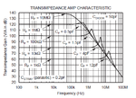
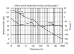
Hi guys, I am reading the TIA product (TI OPA380) data sheet but confused about frequency response of the opamp and its TIA, which are all attached below.

I don't get why the TIA has so large -3db bandwidth. Take Rf= 1k ohms as an example. Ideally, Aclose_loop = 60dB and -3dB bandwidth of TIA showed is 10M Hz. But mathmatically, Acl= Ao/(1+Ao*f) and f=1/Rf. So Acl = Rf/(Rf/Ao+1) and this means when Ao is much larger than Rf, Rf/Ao + 1 ---> 1 and then Acl = Rf roughly. But when the Ao drops with the increasing frequency, the Acl will drop. I guess this is why the -3dB happen.

But in this data sheet, before f<100K Hz, Ao > 60dB=Rf. So before this, the DC gain of TIA still doesnot drop I understand. But after f=100k Hz, Ao begins to drop so I think Acl, the TIA gain, needs to drop.

So my question is how to explain the -3dB bandwidth is so large when compared with Ao. Thanks!
 

Attachments

  • TIA-frequency response.png
    TIA-frequency response.png
    38.5 KB · Views: 169
  • OPAMP-frequency response.png
    OPAMP-frequency response.png
    27.6 KB · Views: 167
  • TIA-system.png
    TIA-system.png
    13.4 KB · Views: 148

OPA380's GBW is 90MHz. Its Aol is 120dB, and this stays so until nearly its GBW frequency. The feedback circuit's -3dB frequencies are (more or less) given by f-3db = 1/2πRF(CF+CSTRAY+CDIODE).

OPA380's Open-Loop Output Impedance RO is 40Ω (correspondingly less in feedback), so all considered feedback resistors don't present any essential load for the output.
 

Thanks for your answer.

The output impedance of open loop is small so that it does not degrade the TIA gain and this is clear now. But I have several points I donot understand:

1. The OPA380' open loop gain is 120dB but it stay only 100Hz and after that it will drop, not stays 120dB until its GBW frequency as you mentioned.

2. What's the relationship between the open loop gain with the closed loop gain? Is it necessary that the open loop gain A0 needs to be larger than close loop gain Rf?

3. What's the relationship between the open loop -3dB frequency and the closed loop -3dB frequency? Is it necessary that the open loop -3dB frequency needs to be larger than the close loop -3dB frequency? Or in another way, at the closed loop -3dB frequency, the open loop gain right there should be larger than the closed loop gain?

From your answer, I see you have already read the data sheet. Thank you!

coxstreet
 

1. The OPA380' open loop gain is 120dB but it stay only 100Hz and after that it will drop, not stays 120dB until its GBW frequency as you mentioned.

You are right: not until its GBW. But - as you can see from the topmost curve of the TRANSIMPEDANCE AMP CHARACTERISTIC - it stays - in this case - at 140dB for more than 10kHz, much farer than 100Hz. The topmost curve (RF=10MΩ) practically depicts the Aol curve, I think.

2. What's the relationship between the open loop gain with the closed loop gain? Is it necessary that the open loop gain A0 needs to be larger than close loop gain Rf?

You've given the context above. Of course Aol ≧ Acl in all frequency ranges considered. Acl cannot be larger than Aol, isn't it? Where Aol is not much greater than Acl (near the -3dB frequency), the feedback loop gain Aol-Acl decreases, and so the accuracy of Acl, RO/loop_gain ...

3. What's the relationship between the open loop -3dB frequency and the closed loop -3dB frequency? Is it necessary that the open loop -3dB frequency needs to be larger than the close loop -3dB frequency? Or in another way, at the closed loop -3dB frequency, the open loop gain right there should be larger than the closed loop gain?

The closed loop -3dB frequency essentially is given by the RC time constant as stated above. The same context regarding Aol is valid as given above. From the transimpedance curves you can see that Aol-Acl ≈ 10dB (in any case >0dB) at the -3dB frequencies.
 

Thank you for your explanations.

1. So, if I want to achieve the tia characteristic as same as the curve of the TRANSIMPENDANCE AMP CHARACTERISITC , I need to design the
the open loop frequency response as same the top curve of the TRANSIMPENDANCE AMP CHARACTERISITC, not the one-frequency response of open loop gain-showed before. Am I right?

2. When it design the open loop frequency response, it uses the load capacitor as large as 50p F. My question is why it want to use such large capacitor? Because large capacitor as well as large UNF-100M Hz- will bring large power consumption, being calculated 200m W.

Thank you for your patience.

Best Regards,

coxstreet
 

1. So, if I want to achieve the tia characteristic as same as the curve of the TRANSIMPENDANCE AMP CHARACTERISITC , I need to design the
the open loop frequency response as same the top curve of the TRANSIMPENDANCE AMP CHARACTERISITC,
Yes. It depends all on how much bandwidth and feedback loop gain Aol-Acl for the required bandwidth you need.

... not the one-frequency response of open loop gain-showed before. Am I right?
I don't remember this one. For such comparison you should provide the appropriate link.

2. When it design the open loop frequency response, it uses the load capacitor as large as 50p F. My question is why it want to use such large capacitor? Because large capacitor as well as large UNF-100M Hz- will bring large power consumption, being calculated 200m W.

Load capacitors as large as 50pF or even more are not wanted, but sometimes (application-dependent) have to be considered. The OPA380 data sheet just shows that this OTA - with its rather low output impedance - is capable to make up with such large capacitive loads.
 
Coxstreet, do you realize that the closed-loop bandwidth - in contrast to the classic opamp - does (primarily) NOT depend on the gain but only on the feedback resistor (as can be seen on the graph)?
 

Coxstreet, do you realize that the closed-loop bandwidth - in contrast to the classic opamp - does (primarily) NOT depend on the gain but only on the feedback resistor (as can be seen on the graph)?

LvW, yes. The closed loop gain ideally is Rf while the classis opamp is equal to the open loop circuit. So the closed loop bandwidth mainly depends on the shunt resistor.
 

Hi erikl,

Thank you!

coxstreet
 

coxstreet said:
By private mail message

Hi Erikl,

Thank you for your explanations of the relationship between TIA open loop gain and closed loop gain. But I do find a last year RFIC paper said the its open loop gain is 250=48dB but its TIA closed loop gain is 25k ohms = 80dB ideally. I am totally confused again. Could you help me have a look on that paper?Thank you!

As I told you above, I can't imagine Acl>Aol . Ok, tell us which paper - or attach it, if you're allowed to do so.

Pls. don't change to PM - stay on the forum, so other interested people could make profit of the thread, too.
 

As I told you above, I can't imagine Acl>Aol . Ok, tell us which paper - or attach it, if you're allowed to do so.

Pls. don't change to PM - stay on the forum, so other interested people could make profit of the thread, too.

Hi Erikl, Thank you! The paper is "A 5 Gbps Low Noise Receiver in 0.13μm CMOS For Wireless Optical Communications", Behrooz Nakhkoob, RFIC,2012. The paper is attached below. As I said, Aol=250=48dB and Acl=25k ohms=80dB. Pls help me have a look. Thank you!

Best,
coxstreet
 

Attachments

  • Low noise receiver for wireless optical communication.pdf
    1.6 MB · Views: 100

Hi coxstreet,
perhaps not important and not new to you - nevertheless, a short hint:

There is nothing like an open-loop "gain" for TIA`s. Instead, they have an open-loop transimpedance Ztr.
 

Hi LvW,

Thanks. Does your open-loop transimpedance Ztr stand for TIA's gain? Thanks.
 

Hi LvW,

Thanks. Does your open-loop transimpedance Ztr stand for TIA's gain? Thanks.

Yes - it is the output-to-input ratio. Thus, it represents the gain properties.
 

RFIC paper said the its open loop gain is 250=48dB but its TIA closed loop gain is 25k ohms = 80dB ideally. I am totally confused again.

I think with the open loop gain of A0 = 250 V/A ≙ 48dB the DC gain of a single gain stage is meant. As there are 3 of them in series, Av0 = |A0|3 = 3*48dB = 144dB , s. p.2 . This is a lot more than the closed loop gain of 25kΩ ≙ 88dB .
 

I think with the open loop gain of A0 = 250 V/A ≙ 48dB the DC gain of a single gain stage is meant. As there are 3 of them in series, Av0 = |A0|3 = 3*48dB = 144dB , s. p.2 . This is a lot more than the closed loop gain of 25kΩ ≙ 88dB.
I think it's different, and quite simple. In contrast to part of this discussion, the RFIC paper puts emphasize on not confusing voltage gain with transimpedance units. You'll notice that it always carries along impedance units with transimpedance. It's clarified that Av = |Ao|³ describes the voltage gain of amplifier block. In numbers, Av is considerably smaller than transimpedance, not hard to achieve for a FET amplifier with effectively infinite current gain.

The same confusion of voltage gain with transimpedance numbers can be already found in the initial post of this thread, possibly brought up by the sloppy terminology of the TI datasheet that measures transimpedance gain in dB rather than dBΩ.
 
Hi FvM, do you mean that the closed loop gain of TIA can be achieved larger than its open loop gain? But it doesnot make sense since Acl=Ao/(1+f*Ao) and f=1/Rf
----> Acl=Rf/(Rf/Ao+1). Can you explain a little more details about that? Thanks.

Cox
 

Hi FvM, do you mean that the closed loop gain of TIA can be achieved larger than its open loop gain?
No I meaned that voltage gain numbers (unit V/V) can't be compared to transimpedance numbers (unit V/A).
 

OK. So, do you mean mean that if I want to design a 80dB ohms transimpedance gain of TIA, I can both design a 90dB OR 70dB main amplifier (OPAMP in TIA) to achieve that? Thanks.

Cox
 

Hi Erikl, I think we made a mistake at the beginning. The transimpedance gain of TIA should not be compared with its openloop gain by just so simple way. Smaller openloop gain still can have large TIA gain.

My TIA transfer function is wrong. It should be (for first order system) Vout/Iin=[-Ao/(Ao+1)] * [Rf/(1+Rf*Cdiode*s/(A+1)] (This is from Razavi's "Design of Integrated circuits for optical communication", 2th, Pg 87). So for this equation, at the low frequency, Vout/Iin= [-Ao/(Ao+1)] * Rf and thus A0>>1 then Vout/Iin=Rf. A0 can be no larger than Rf to achieve this.

For the TI data sheet, I use one OPAMP has dc_Gain=45dB to achieve TIA's Rf=100k ohms without no degrades.

Anyway, thank you so much!

Cox

- - - Updated - - -
 

Attachments

  • TIA first order.png
    TIA first order.png
    33.2 KB · Views: 182
  • Like
Reactions: erikl

    erikl

    Points: 2
    Helpful Answer Positive Rating
Status
Not open for further replies.

Part and Inventory Search

Welcome to EDABoard.com

Sponsor

Back
Top