poorren
Junior Member level 3

- Joined
- Jan 15, 2011
- Messages
- 27
- Helped
- 1
- Reputation
- 2
- Reaction score
- 1
- Trophy points
- 1,283
- Activity points
- 1,656
Folks,
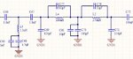
Here's a bandpass filter with upper/lower corner frequency around 30Mhz/3Mhz. Because the bandwidth is much wider than center
frequency, it actually constructs by cascading a 30Mhz lowpass with 3Mhz highpass. The simulated response meets my expectation.
However, when trying to implement that filter, I want to make a bit optizimation on that big inductor (2.2uH) and small cap
(10pF/22pF). Yes, I could do nothing but directly implement them. It's implementable.
My question is whether there's some method to convert shunted series-LC section or series shunted-LC section to some more
convenient value. I know the norton transform has the ability to simplify circuit, however, I don't know if it could be applied to these structures.
Do anyone have some suggestion on that? Thanks advance!