Continue to Site

Welcome to EDAboard.com

Welcome to our site! EDAboard.com is an international Electronics Discussion Forum focused on EDA software, circuits, schematics, books, theory, papers, asic, pld, 8051, DSP, Network, RF, Analog Design, PCB, Service Manuals... and a whole lot more! To participate you need to register. Registration is free. Click here to register now.

Question of pulse width doubler

Status
Not open for further replies.

bhl777

Full Member level 6
Joined
Sep 30, 2008
Messages
363
Helped
0
Reputation
0
Reaction score
0
Trophy points
1,296
Activity points
5,140
Hi all, if I have a randomly generated pulses (duty cycle <50%) as the input, how can I use simple logic circuit to generate an output pulse, whose pulse width is twice of that of the input pulse? Thank you! pulse width doubler.png
 

What is the minimum time between the falling edge of the one pulse to the rising edge of the following pulse?
What frequency or repetition rate is involved?
 

the frequency is typically around 300kHz to 600kHz, and duty cycle is less than 50%. So there is no problem of the overlap between the doubled pulse and the rising of the next cycle. Thank you!
What is the minimum time between the falling edge of the one pulse to the rising edge of the following pulse?
What frequency or repetition rate is involved?
 

The feasibility of this depends on the range of pulse widths.

But how about an up/down counter that counts up during the pulse duration, then counts back down ?
This is going to take more than a bit of "simple" logic.
 

How accurate does the "twice" have to be and what resolution is required?
That will determine the circuit complexity required.
It certainly won't be "simple".
 

The feasibility of this depends on the range of pulse widths.

But how about an up/down counter that counts up during the pulse duration, then counts back down ?
This is going to take more than a bit of "simple" logic.

Would you teach me how to do it? The pulse width will be around 300ns and above, not necessarily exact twice.

- - - Updated - - -

How accurate does the "twice" have to be and what resolution is required?
That will determine the circuit complexity required.
It certainly won't be "simple".

The pulse width will be around 300ns and above, not necessarily exact twice. Would you teach me how to do it?
 

Would you teach me how to do it? The pulse width will be around 300ns and above, not necessarily exact twice.
300nS is too fast for the up/down counter approach.
If it was 300mS or even 300 uS it might have been possible.
 

Can you explain more about the application you need this for and why? That will give all of us a better idea what you are trying to do.

I was thinking about a bidirectional current source charging/discharging a capacitor with a comparator that trips near the zero point, but that may be too slow as well. This way the you get double the pulse width with a small error.
 

Attachments

  • pulsew_doubler.png
    pulsew_doubler.png
    28.6 KB · Views: 94
  • Like
Reactions: bhl777

    bhl777

    Points: 2
    Helpful Answer Positive Rating
A simple DCR arrangement works (approximately) if duty cycle is short. The capacitor and potentiometer values are determined by experimentation. The aim is to adjust capacitor charge/discharge so it goes above 2.5 V for a portion of the cycle which is proportionate to pulse length.

 
  • Like
Reactions: bhl777

    bhl777

    Points: 2
    Helpful Answer Positive Rating
I was thinking about a bidirectional current source charging/discharging a capacitor with a comparator that trips near the zero point, but that may be too slow as well. This way the you get double the pulse width with a small error.
This would be also my solution. An accuracy of e.g. 1 % of the pulse period (about 20 ns) should be achievable with regular analog design, even ns range with really fast components. On the other hand, 5 or 10 ns ís no problem with standard programmable logic, could think of a single chip solution with a recent flash based FPGA.

A simple DCR arrangement works (approximately) if duty cycle is short. The capacitor and potentiometer values are determined by experimentation. The aim is to adjust capacitor charge/discharge so it goes above 2.5 V for a portion of the cycle which is proportionate to pulse length.
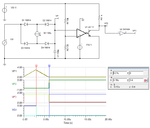
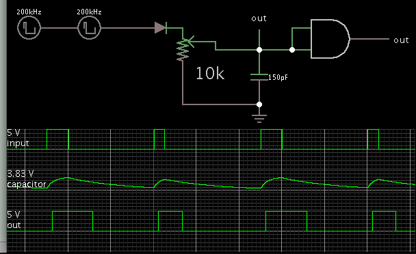
The capacitor charge/discharge most stay in a small (approximately) linear part of the exponential curve. Otherwise the intended fixed pulse width relation can't be achieved. It's better to use current sources.
 
  • Like
Reactions: bhl777

    bhl777

    Points: 2
    Helpful Answer Positive Rating
Below is the LTspice simulation of an analog pulse stretcher circuit.
It uses two complementary constant-current-mirrors and a fast comparator.
The two current mirrors are alternately turned on and off by the input signal.
The transistors must be fast switching types, otherwise saturation delays can be a problem.
The circuit inverts the input so there needs to be an inverter added at the input if that is not desired.
Pot U2 adjusts the pulse width to be twice the input width.
The simulation is shown for input widths of 300ns and 1.5µs, giving output widths of ≈ 600ns and 3µs.

Pules stretcher.PNG

- - - Updated - - -
 
Last edited by a moderator:
Just noticed a couple of typos in my #11 thread and I can't correct them because of the annoying and odd time limitation on editing ones own threads on this site (which the other two sites I frequent don't have. :-?

But anyway, the second line should be:
It uses two complementary constant-current-mirrors and a fast comparator.
and the second to last line should be:
The simulation is shown for input widths of 300ns and 1.5µs,...
 

Status
Not open for further replies.

Part and Inventory Search

Welcome to EDABoard.com

Sponsor

Back
Top