Continue to Site

Welcome to EDAboard.com

Welcome to our site! EDAboard.com is an international Electronics Discussion Forum focused on EDA software, circuits, schematics, books, theory, papers, asic, pld, 8051, DSP, Network, RF, Analog Design, PCB, Service Manuals... and a whole lot more! To participate you need to register. Registration is free. Click here to register now.

Question of LM723-Floating Postive Regulator.

Status
Not open for further replies.

jigshaw

Member level 1
Joined
Jul 4, 2009
Messages
41
Helped
3
Reputation
6
Reaction score
3
Trophy points
1,288
Location
China
Activity points
1,520
Has anyone appicated LM723 with floating positive regulator?
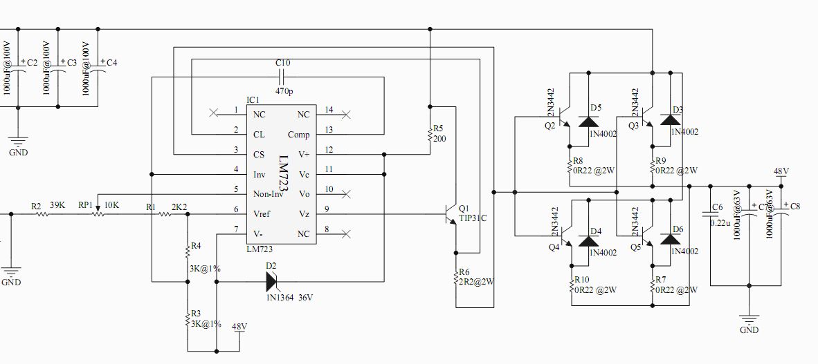
This circuit was a typical floating positive regulator from datasheet of LM723_NS.
LM723_Floating.png
I use this circuit in my design to get a linear 48V regulator with 83V unregulated DC input.
But it does not work at all.
The Vref pin output with an unstable voltage about 74V to ground and the output always gives unstable output range from 80 to 82V.
When with load (approximately 1A) connected,the output drops to 0V immediately.
The ouput will increase to 80 V slowly after load moved away.

The only difference in my circuit is I using 1N5365B(5W,36V) zender instead of 1N1364(10W,36V).
Can anyone give me some suggestions?
Thanks.
 

What are the values used for R1 and R2? Is R1 connected properly? Try put a filter capacitor 47uF in paralell to zener diode
 
Last edited:

What are the values used for R1 and R2? Is R1 connected properly? Try put a filter capacitor 47uF in paralell to zenere diode

I use R1=2.2k , R2=39k plus an RP=10k between these two resistors for output of 48V.

Thanks.


I tried your method,it did not work.:-?
 
Last edited:

Well there are a number of problems, but one to start with is that you will have (83-48) *1= 35 watts dissipated in the pass transistor, so it had better be heat sunk.

Another problem is that your zener diode would dissipate around 7 watts with that 200 ohm resistor. Since it can not do that without blowing up, you probably blew the 723 chip. Change the 200 ohm resistor to maybe 2.2K.

There might be insufficient drive for the base of the pass transistor to make 1 amp. You might want a fet or darlington transistor there.

Also the 1 ohm current sense resistor seems a little big---it might be tripping the overcurrent protection. Try making that .2 ohms.

Well.Thanks.
I just did not consider the last problem. I used 2.2Ohm of current sense,since I used two stage amplifier with TIP31C and 2N3442.So I suppose it won't acitivate overcurrent protection.
I replaced the original zender diode with 1N5365(36V,5W) and a resistor of 400 Ohm.
I tested my circuit.
There's only 9 volts between Vc and V-.Most of the potential is on the floating ground,that is output port.
The output from Vz or Vo is not stable.

The figure below is the circuit I am using,R5 was replaced with 400 Ohm.
 

I use this circuit in my design to get a linear 48V regulator with 83V unregulated DC input.
But it does not work at all.

Did you check the maximum input volts on the datasheet ? It says 40 volts maximum input, see here:
723.jpg
This datasheet is from NSC. If you apply 83 volts as input, will it not roast the IC?
 

Circuit seems ok but only before when overload is activated and transistor is turned off, 50V drop across 200 ohm resistor.It happens when there is inrush of current to charge capacitors. CS can stay not connected and R6 increased.
The Input is 83V, ouput is 48V so voltage drop on zener is less than 35V. Zener is of 36V so in normal operation there is no current through zener. In this mode, it is used upto 250V. See table 1 and 2 for fig.7 tn this datasheet.
 

Attachments

  • uA723.pdf
    254.5 KB · Views: 107
Last edited:

Did you check the maximum input volts on the datasheet ? It says 40 volts maximum input, see here:
View attachment 65351
This datasheet is from NSC. If you apply 83 volts as input, will it not roast the IC?

That's why we call it "floating positive regulator".
The V- set at a potential that not zero to the ground and ensure the volt between V+ and V- lower than 40V.

---------- Post added at 01:26 ---------- Previous post was at 01:22 ----------

Circuit seems ok but only before when overload is activated and transistor is turned off, 50V drop across 200 ohm resistor.It happens when there is inrush of current to charge capacitors. CS can stay not connected and R6 increased.
The Input is 83V, ouput is 48V so voltage drop on zener is less than 35V. Zener is of 36V so in normal operation there is no current through zener. In this mode, it is used upto 250V. See table 1 and 2 for fig.7 tn this datasheet.

I considered that problem also yestoday and bought zender of 12v & 24v. I would try it today.
Thanks for your guys.:smile:
 

Sorry my mistake for over looking some part of the datasheet.
 

Status
Not open for further replies.

Similar threads

Part and Inventory Search

Welcome to EDABoard.com

Sponsor

Back
Top