Continue to Site

Welcome to EDAboard.com

Welcome to our site! EDAboard.com is an international Electronics Discussion Forum focused on EDA software, circuits, schematics, books, theory, papers, asic, pld, 8051, DSP, Network, RF, Analog Design, PCB, Service Manuals... and a whole lot more! To participate you need to register. Registration is free. Click here to register now.

Question about zero and pole in analog circuits

Status
Not open for further replies.

SDRookie

Junior Member level 2
Joined
Aug 23, 2017
Messages
22
Helped
0
Reputation
0
Reaction score
0
Trophy points
1
Activity points
273
I know the def of zero is at that frequency the output is 0 and pole is the output become infinity.

I am confused about why pole will cause the bode plot decrease 20dB/decade and zero will increase 20dB/decade.
 

I am confused about why pole will cause the bode plot decrease 20dB/decade and zero will increase 20dB/decade.
Because that is what you get when you do the math.
 

There is a lot of depth and complexity to the terms 'pole' and 'zero' but there are many ways to understand what they mean.

Understand that a simple example of a pole is an RC filter. Below a certain frequency the filter passes the input to the output with negligible attenuation. Above a certain frequency (the frequency of the pole or the cutoff frequency) the output starts getting attenuated and it gets attenuated by 20dB/decade as the frequency increases.

A high pass filter is a simple example of a zero which is similar but opposite in terms of the frequency response. Integrators and differentiators are also trivial examples of poles and zeros.

The 20db/decade follows from the basic physics of these examples and the math details that. If you're going to study this further get familiar with tools that can simulate or calculate this stuff for you. LTSpice has great AC sim of analog circuits and is free. Sapwin gives you the algebraic S domain transfer function from a schematic and Microsoft Mathematics (symbolic algebraic solver) is a shortcut for the math.
 

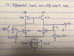
IMG_0869.jpg

This is the schematic of a differential amplifier

there are a pole and a zero at capacitor CA

- - - Updated - - -

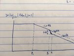
this is the bode plot of the circuit
I don't understand why pole-zero doublet causes 6dB difference

IMG_0870.jpg
 

Consider a simple function f(z)=z (usually z is used when we consider a complex number but x is equally ok in this example).

This function has a zero when z=0. If the initial function is something like f(z)=z-a then the function will have a zero at z=a. This function has no poles.

Consider a rational function f(z)=(z-a)/(z-b); this function has a zero when z=a and also has a pole at z=b. The function becomes infinite at z=b. This is a first order pole.

Consider a similar example f(z)=(z-a)/((z-b)*(z-c)); it has two poles at z=b and z=c (also zero is at z=a). If b=c, we will have a second order pole.

In electrical circuits, z can be represented by current and voltage. In AC circuits, both voltage and current are associated with their respective phases and that makes matters interesting...

Perhaps you can now correlated order of filters with poles ...
 

Status
Not open for further replies.

Similar threads

Part and Inventory Search

Welcome to EDABoard.com

Sponsor

Back
Top