Continue to Site

Welcome to EDAboard.com

Welcome to our site! EDAboard.com is an international Electronics Discussion Forum focused on EDA software, circuits, schematics, books, theory, papers, asic, pld, 8051, DSP, Network, RF, Analog Design, PCB, Service Manuals... and a whole lot more! To participate you need to register. Registration is free. Click here to register now.

Question about Colpitts oscillator theory

Status
Not open for further replies.

obrien135

Full Member level 5
Joined
Nov 10, 2009
Messages
240
Helped
5
Reputation
10
Reaction score
5
Trophy points
1,298
Location
Connecticut
Activity points
3,259
Hello,

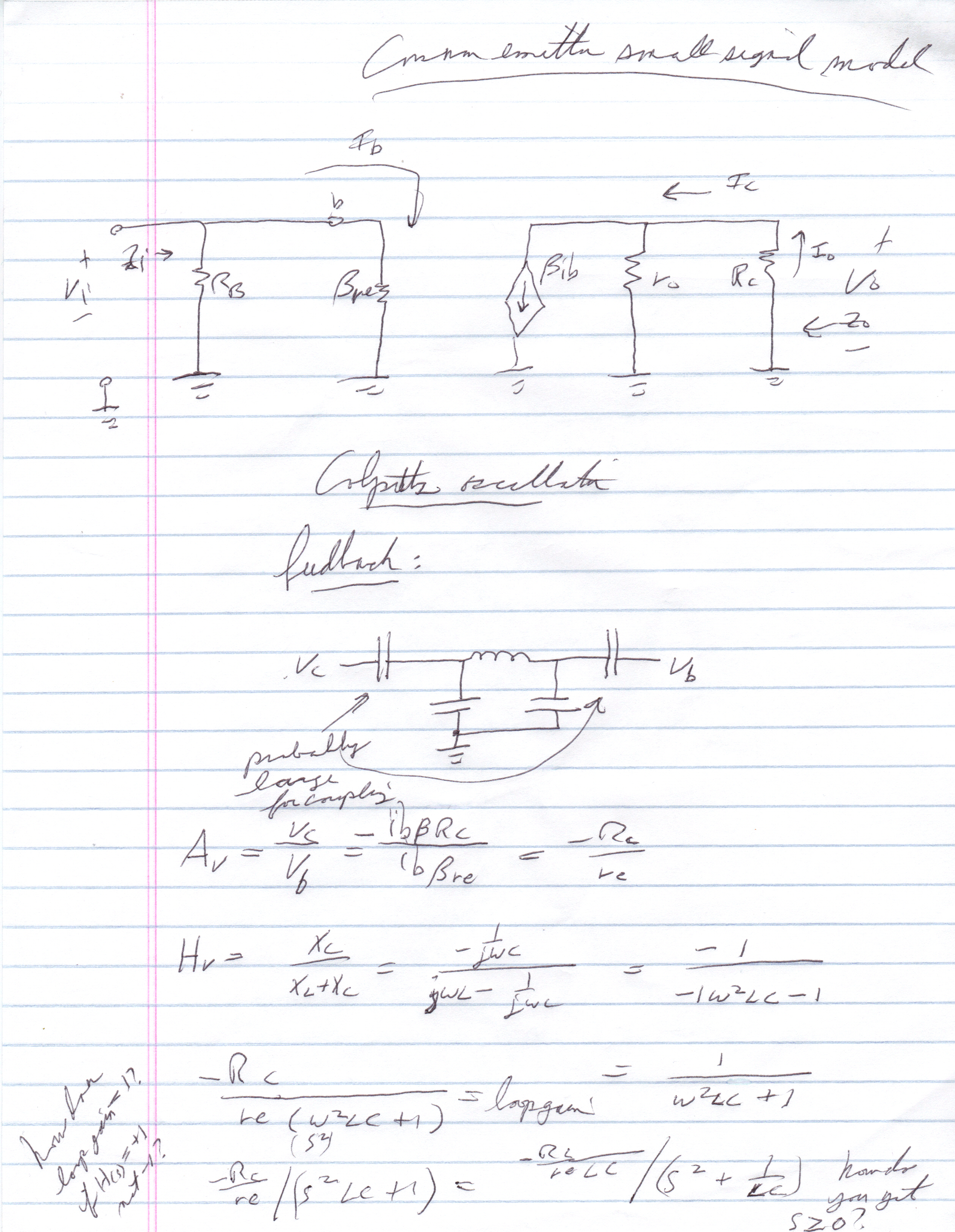
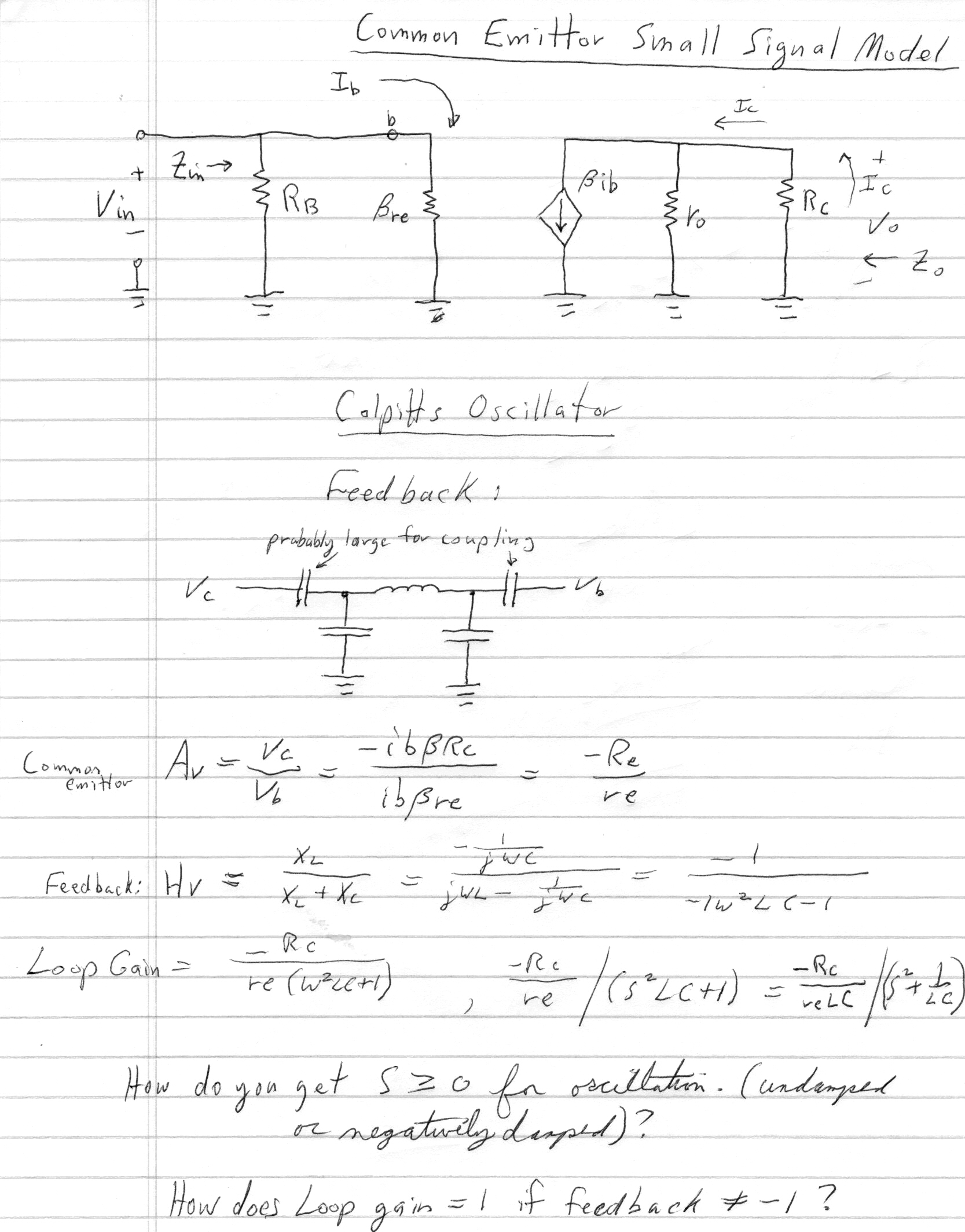
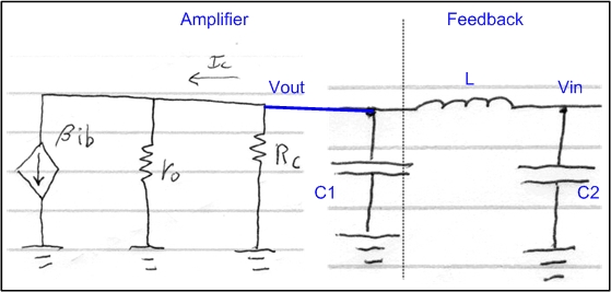
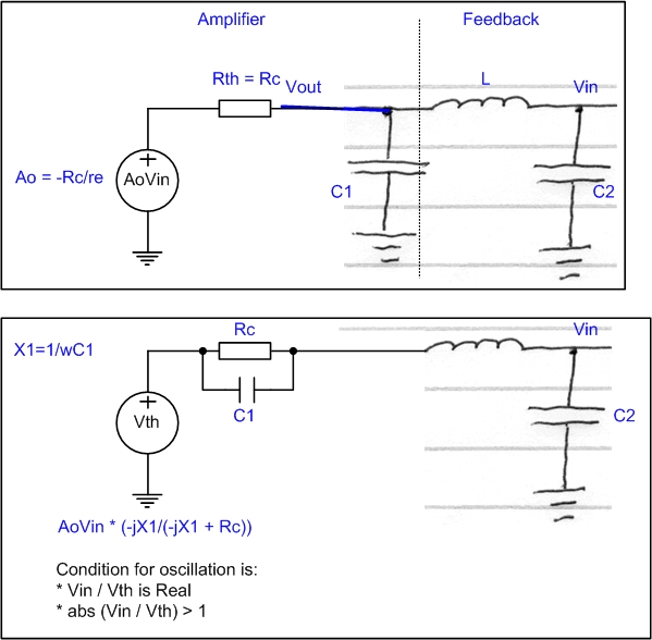
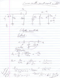
I tried to analyse a colpitts oscillator based on common emittor small signal model and analyses of feedback / phase changeing network. I don't know if I got the equation for voltage gain in a common emittor amplifier right, my text book is in the basement right now. I have to find it. But the calculations I did are shown on the attached sheet. The question is, how is a phase shift of zero achieved and how do you get a transfer function with a pole that has a real component >= 0 so it will be unstable and therefore oscillate?


Your handwritten paper is not readable.
 

Maybe this one is a little clearer.


Hi obrien135,

When making the loop gain you are forgetting the effect of first capacitor of the pi-network (let's say
C1), which is charging the ouput of the amplifier section (at transistor collector).

Possibilities to solve this:
1) Use C1 as part of load of your amplifier, in parallel with Rc --> you will get a complex gain for the amplifier section and a complex number at the gain loop --> then you force the imaginary part to 0 to get the oscillation condition (the frequency for which the phase shift is 0)

2) Use the Thevening equivalent for your amplifier output and then complete it with the feeback network (pi-network) --> Thevening schematic are usually more friendly to use (may be it is just a matter of visual).

Don't be afraid to repeat the Thevening but this time with C1, which will lead again to a complex Vthevening (Vth). The Rth will also be complex. --> Now you have all impendances and resistances in series with Vth, which allows you to easily calculate the voltage transfer.

At the end you shoul reach the following oscillation condition: Ao > C2/C1, where Ao=Rc/re
-----------------------------------------------

This conceptual problem is coming from the theory where it is said that for getting oscillations, (Ao)B>1 where Ao is the amplifier gain in open loop. But even in open loop, you have to considere the possible charges that could be attached to the output (C1 in this case). the same thing sould be said for the end the feedback where to mathematically more near of reality, the Beta*re resistance should have been shown just in parallel with C2. This has not been done and it is justified as far as we can demonstrate that Beta*re >> X2 (=1/wC2) at the osciallation frequence, which is usually the case in common-emmitter configurations (you can check this - take the challenge)

Note that you can not remove C1 because in that case there will not be a 180 phase shift and oscillations will never occur.

Hope it helped a little bit.

 
Last edited:

Add at least the Rs of the coil (from its Q). Keep in mind that is only a small signal, startup conditions analysis. Steady state will be large signal model on BJT.
 

Status
Not open for further replies.

Part and Inventory Search

Welcome to EDABoard.com

Sponsor

Back
Top