Continue to Site

Welcome to EDAboard.com

Welcome to our site! EDAboard.com is an international Electronics Discussion Forum focused on EDA software, circuits, schematics, books, theory, papers, asic, pld, 8051, DSP, Network, RF, Analog Design, PCB, Service Manuals... and a whole lot more! To participate you need to register. Registration is free. Click here to register now.

[SOLVED] Query : No display on monitor ( 800*600 resolution ) VGA CONTROLLER BASYS 2 BOARD

Status
Not open for further replies.

sukanya28

Junior Member level 2
Joined
Oct 1, 2014
Messages
23
Helped
0
Reputation
0
Reaction score
0
Trophy points
1
Activity points
213
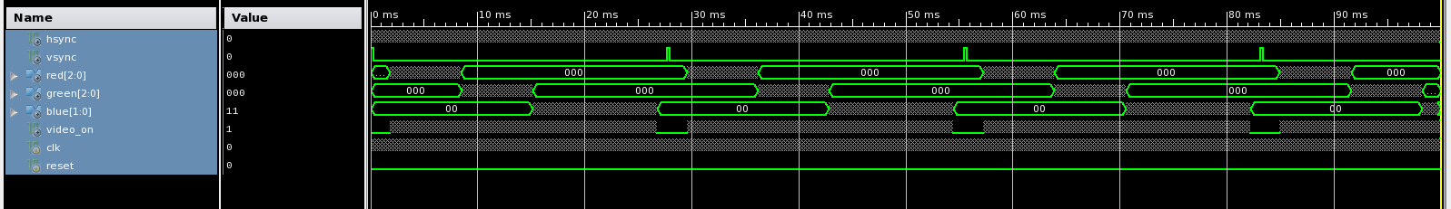
Hi, I am not getting any result for my code ( VGA Controller 800*600 res ) which is properly synthesized and has no errors. The code is as follows and I have attached test bench and ucf file too. Please help.

Code :

Code:
module anymodule(input wire clk,reset,
output wire hsynch,vsynch,
output [2:0] red,
output [2:0] green,
output [1:0] blue,
output video_on);
	 

// defining constants
localparam HD = 800; // horizontal display area
localparam HF = 56; // front porch (right border)
localparam HB = 64; //right porch (left border)
localparam HR = 120; // horizontal retrace
localparam VD = 600; // vertical display area
localparam VF = 37; // front porch (bottom border)
localparam VB = 23; // back porch (top border)
localparam VR = 6; // vertical retrace


//horizontal and vertical counter

reg [9:0] h_count = 0;
reg [9:0] v_count = 0;
wire [9:0] h_end,v_end;

assign h_end = HD+HF+HR+HB-1;
assign v_end = VD+VF+VR+VB-1;


always @(clk)
if(h_count<h_end)
h_count <= h_count+1;
else
h_count <= 0;


always @(*)
if(clk & h_end)
if(v_count<v_end)
v_count <= v_count+1;
else
v_count <= 0;
else
v_count <= v_count;


assign hsynch = ((h_count>= HD+HF-1) && (h_count<=HD+HF+HR+HB-1));
assign vsynch = ((v_count>=VD+VF-1) && (v_count<= VD+VF+VR+VB-1));
assign video_on = ((h_count <HD) && (v_count<VD));

wire [9:0] pixel_x,pixel_y;
assign pixel_x = (video_on)? h_count : 10'b0;
assign pixel_y = (video_on)? v_count : 10'b0;


reg [7:0] coloroutput;


always @(clk)
if(~video_on)
coloroutput <= 0;
else
begin
if( pixel_x<150 && pixel_y<160)
coloroutput[7:5] <= 3'b111;
else if(pixel_x<250 && pixel_y<320)
coloroutput[4:2] <= 3'b111;
else
coloroutput[1:0] <= 2'b11;
end


assign red = (video_on)?coloroutput[7:5] : 3'b000;
assign green = (video_on)?coloroutput[4:2] : 3'b000;
assign blue = (video_on)?coloroutput[1:0] : 3'b000;


endmodule
 

Attachments

  • ucf_vga.txt
    301 bytes · Views: 63
  • testbench_vga.txt
    688 bytes · Views: 65
Last edited by a moderator:

You're performing an AND operation with a clock and a bus?

Code:
if (clk & h_end)
what do you expect this bitwise AND to evaluate to?

Using the clock in this fashion is not a good design practice in FPGAs.

You are also using non-blocking statements in a combinational always block:
Code:
always @(*)
  if(clk & h_end)
    if(v_count<v_end)
      v_count <= v_count+1;
    else
      v_count <= 0;
  else
    v_count <= v_count;
In this case the non-blocking assignments are not going to result in problems, but you should always use blocking assignments in always @* blocks to avoid synthesis/simulation mismatches. It's also not going to synthesized correctly as it has a counter embedded in it.

I tried to run your testbench and design in Vivado xsim and it throws out an iteration limit error. That error is a result of the clk & h_end always evaluating to true once clk goes high, which results in that always block being triggered continuously as v_count is always changing.

You need to get rid of the combinational always block. Counters should only be used in sequential always blocks.

Regards
 

Hi, I have made these corrections. Please have a look.

Code:
always @(*)
begin
if(clk)
  if(h_end)
    h_count = 0;
  else
h_count = h_count+1;
else
h_count = h_count;
end

always @(clk)
begin
  if(h_end) 
	 if(v_count<v_end)
          v_count = v_count+1;
    else
           v_count = 0;
   else
          v_count = v_count;
end
 

[Merge]VGA Controller (Simulation is correct but no display on monitor) BASYS 2 BOARD

Hi, I have attached the snapshot of the waveforms generated through simulation of my VGA CONTROLLER ( 800*600 resolution ). snapshot 1.PNG
The 2 output's hsync and vsync are displayed '0' and I have no idea that why is it so. Please help.

Code :

Code:
module anymodule(input wire clk,reset,
output wire hsynch,vsynch,
output [2:0] red,
output [2:0] green,
output [1:0] blue,
output video_on);
	 

// defining constants
localparam HD = 800; // horizontal display area
localparam HF = 56; // front porch (right border)
localparam HB = 64; //right porch (left border)
localparam HR = 120; // horizontal retrace
localparam VD = 600; // vertical display area
localparam VF = 37; // front porch (bottom border)
localparam VB = 23; // back porch (top border)
localparam VR = 6; // vertical retrace


//horizontal and vertical counter

reg [9:0] h_count = 0;
reg [9:0] v_count = 0;
wire [9:0] h_end,v_end;

assign h_end = HD+HF+HR+HB-1;
assign v_end = VD+VF+VR+VB-1;


always @(*)
begin
if(clk)
  if(h_end)
    h_count = 0;
  else
h_count = h_count+1;
else
h_count = h_count;
end

always @(clk)
begin
  if(h_end) 
	 if(v_count<v_end)
          v_count = v_count+1;
    else
           v_count = 0;
   else
          v_count = v_count;
end


assign hsynch = ((h_count>= HD+HF-1) && (h_count<=HD+HF+HR+HB-1));
assign vsynch = ((v_count>=VD+VF-1) && (v_count<= VD+VF+VR+VB-1));
assign video_on = ((h_count <HD) && (v_count<VD));

wire [9:0] pixel_x,pixel_y;
assign pixel_x = (video_on)? h_count : 10'b0;
assign pixel_y = (video_on)? v_count : 10'b0;


reg [7:0] coloroutput;


always @(clk)
if(~video_on)
coloroutput <= 0;
else
begin
if( pixel_x<150 && pixel_y<160)
coloroutput[7:5] <= 3'b111;
else if(pixel_x<250 && pixel_y<320)
coloroutput[4:2] <= 3'b111;
else
coloroutput[1:0] <= 2'b11;
end


assign red = (video_on)?coloroutput[7:5] : 3'b000;
assign green = (video_on)?coloroutput[4:2] : 3'b000;
assign blue = (video_on)?coloroutput[1:0] : 3'b000;


endmodule
 

Explain what the following code is supposed to be used for:
Code:
always @(*) begin
  if(clk)
    if(h_end)
      h_count = 0;
    else
      h_count = h_count+1;
  else
    h_count = h_count;
end
If you commented your code then I wouldn't have to ask.
Regardless this circuit was never designed. What is this code supposed to do?

Well when clk is 1 a high level and the value h_end (which is a non zero constant) always evaluates to a TRUE the h_count is set to 0. If that branch wasn't always taken then the h_count = h_count+1 would have been taken and you would have ended up with a iteration limit exceeded. Did you read my previous post #2? I told you that counters inside combinational always blocks are not synthesizable and they won't simulate due to being an infinite iteration loop (they don't stabilize to a single value).

vsynch works you just need to run your simulation longer, didn't you figure out before hand how long it would take to see the first vsynch?.

Using a clock as a gate control is a really bad design practice. Unless you are a very experienced design engineer and thoroughly understand timing and how to design circuits with clock gating I would avoid clock gating altogether. As a novice I would stick to purely combinational circuits (no clocks) or fully synchronous circuits (everything clocked).

Regards

- - - Updated - - -

You're also still using BLOCKING assignments for v_count. Use non-blocking assignments when using always @(posedge clk).
 

Okay I might have understood what you are trying to say. So I made the changes in the counter used to generate hsynch and vsynch. The counter module is as follows.

Code:
module counter( input wire clk,reset,
output reg h_count_next , v_count_next
    );

// defining constants
localparam HD = 800; // horizontal display area
localparam HF = 56; // front porch (right border)
localparam HB = 64; //right porch (left border)
localparam HR = 120; // horizontal retrace
localparam VD = 600; // vertical display area
localparam VF = 37; // front porch (bottom border)
localparam VB = 23; // back porch (top border)
localparam VR = 6; // vertical retrace


//horizontal and vertical counter


reg [9:0] h_count_reg;
reg [9:0] v_count_reg ;
reg v_sync_reg , h_sync_reg ;
// wire v_sync_next , h_sync_next ;

wire h_end , v_end;


always @ ( posedge clk , posedge reset)
if (reset)
begin
v_count_reg <= 0;
h_count_reg <= 0 ;
end
else
begin
v_count_reg <= v_count_next;
h_count_reg <= h_count_next;

end


assign h_end = (h_count_reg==(HD+HF+HB+HR-1)) ;

assign v_end = (v_count_reg==(VD+VF+VB+VR-1)) ;


// below is the counter used to generate hsynch
always @(*)
if (clk)  //50 Mhz pixel clock
    if(h_end)
      h_count_next = 0 ;
   else
      h_count_next = h_count_reg + 1;
else
h_count_next = h_count_reg;		

//counter used to generate vsynch
always @(*)
if(clk & h_count_reg == h_end)
  if(v_count_reg == v_end)
      v_count_next = 0;
	   else
      v_count_next = v_count_reg+1;
 else
	 v_count_next = v_count_reg;


endmodule


now horizontal counter is running but the vertical counter still shows no simulation i.e it shows 0. I don't understand where I am wrong.
 

You havent changed the code. You are still using blocking assignemings and you are using the clock as a logic signal.

You I suggest changing the always blocks to:

always @(posedge clk)

and changing the logic to non-blocking:

h_count <= h_count + 1;
 

For VGA controller I have made this sync module but as said earlier only horizontal counter is running and not vertical counter. Also when I go on assigning values to signals hsynch and vsynch, their simulations are shown at logic z level. I still don,t understand where I am going wrong. I think I have removed all non blocking assignments as suggested in message #2. The module is as follows:
Code:
module counter( input wire clk,reset,
output wire hsync , vsync

    );

// defining constants
localparam HD = 800; // horizontal display area
localparam HF = 56; // front porch (right border)
localparam HB = 64; //right porch (left border)
localparam HR = 120; // horizontal retrace
localparam VD = 600; // vertical display area
localparam VF = 37; // front porch (bottom border)
localparam VB = 23; // back porch (top border)
localparam VR = 6; // vertical retrace


//horizontal and vertical counter


reg [9:0] h_count_reg ,h_count_next;
reg [9:0] v_count_reg , v_count_next;
reg v_sync_reg , h_sync_reg ;
wire v_sync_next , h_sync_next ;

wire h_end , v_end;


always @ ( posedge clk , posedge reset)
if (reset)
begin
v_count_reg <= 0;
h_count_reg <= 0 ;
v_sync_reg <= 'b0;
h_sync_reg <= 'b0;
end
else
begin
v_count_reg <= v_count_next;
h_count_reg <= h_count_next;
v_sync_reg <= v_sync_next ;
h_sync_reg <= h_sync_next ;
end


assign h_end = (h_count_reg==(HD+HF+HB+HR-1)) ;

assign v_end = (v_count_reg==(VD+VF+VB+VR-1)) ;


// below is the counter used to generate hsynch
always @(*)
if (clk)  //50 Mhz pixel clock
    if(h_end)
      h_count_next = 0 ;
   else
      h_count_next = h_count_reg + 1;
else
h_count_next = h_count_reg;        

//counter used to generate vsynch
always @(*)
if(clk & h_count_reg == h_end)
  if(v_count_reg == v_end)
      v_count_next = 0;
       else
      v_count_next = v_count_reg+1;
 else
     v_count_next = v_count_reg;
    
assign h_sync_next = (h_count_reg >= (HD+HF) && h_count_reg <= (HD+HF+HR-1));
assign v_sync_next = (v_count_reg >= (VD+VF) && v_count_reg <= (VD+VF+VR-1));


assign hsync = h_sync_reg;
assign vsync = v_sync_reg;    


endmodule
 

Everything from assign h_end = (h_count_reg==(HD+HF+HB+HR-1)) ; and onwards still looks pretty combinational to me.

You listened to 50% of the advice, so that's progress. Now the other 50%.

You need to get rid of the combinational always block. Counters should only be used in sequential always blocks.

Because indeed, you have fixed the combinational section from "that does not work" to "at least the right syntax, but not a good idea". So now's the time for that other 50% of the advice already given and turn it into a design that is a good idea.

As ads-ee said, things like counters are better implemented like:

Code Verilog - [expand]
1
2
3
4
always @(posedge clk) begin
    counter <= counter + 1'd1;
end
//etc


the assign h_end .. you can probably get rid of it. The always @(*) combinationals, get rid of it. Sequential always blocks should do the trick just fine.

Random link: https://www.doulos.com/knowhow/verilog_designers_guide/sequential_always_blocks/
 

Don't use clocks as part of if statements.
Code:
if (clk)  //50 Mhz pixel clock
if(clk & h_count_reg == h_end)

Using a clock in this fashion makes a design which is difficult to implement in both Altera and Xilinx (probably most other FPGAs too). It is also much more difficult to perform STA on the design.

Basically don't use clocks except in the following code:
Code:
always @ (posedge clk)
// or
always @ (negedge clk)

Unless you are very experienced and understand the pitfalls using clocks in the logic fabric then avoid using them that way until you gain that level of experience.

Regards
 

The number of bits in your counters are incorrect, h_count_reg & v_count_reg should be more than 10-bits wide.
Code:
// defining constants
localparam HD = 800; // horizontal display area
localparam HF = 56; // front porch (right border)
localparam HB = 64; //right porch (left border)
localparam HR = 120; // horizontal retrace
localparam VD = 600; // vertical display area
localparam VF = 37; // front porch (bottom border)
localparam VB = 23; // back porch (top border)
localparam VR = 6; // vertical retrace

/* These need to change based on your constants above. */
reg [9:0] h_count_reg;
reg [9:0] v_count_reg;

There are multiple other problems as well. This code will not display video, your hsync and vsync timing are not correct.

- - - Updated - - -

Here's some help with your vsync.
Code:
   //counter used to generate vsynch
   always @ (*)
     if(v_end && h_end)
       v_count_next = 0;
     else
       if(h_end)
	 v_count_next = v_count_reg+1;
       else
	 v_count_next = v_count_reg;

Things still aren't perfect, but it's better.
 
Last edited:

Hi, this is my final code. The signals are high throughout for output's hsync and vsync, but r,g,b are not displayed at all. Please help me with this code. I have attached the testbench too.

Code:
module vga_controller(input wire clk,reset,
output wire hsync,vsync,
output [2:0] red,
output [2:0] green,
output [1:0] blue,
output reg video_on);
	 

// defining constants
localparam HD = 800; // horizontal display area
localparam HF = 56; // front porch (right border)
localparam HB = 64; //right porch (left border)
localparam HR = 120; // horizontal retrace
localparam VD = 600; // vertical display area
localparam VF = 37; // front porch (bottom border)
localparam VB = 23; // back porch (top border)
localparam VR = 6; // vertical retrace
localparam h_end = 1040; 
localparam v_end = 666;


//horizontal and vertical counter

reg [10:0] h_count_reg,v_count_reg ;
reg[10:0] h_count_next , v_count_next;
//reg v_sync_reg , h_sync_reg ;
//wire v_sync_next , h_sync_next ;
reg v_sync_next , h_sync_next = 0 ;


always @ ( posedge clk , posedge reset)
if (reset)
begin
v_count_reg <= 0;
h_count_reg <= 0 ;
//v_sync_reg <= 1'b0;
//h_sync_reg <= 1'b0;
end
else
begin
v_count_reg <= v_count_next;
h_count_reg <= h_count_next;
//v_sync_reg <= v_sync_next ;
//h_sync_reg <= h_sync_next ;
end

// horizontal and vertical counters
always @(posedge clk) 
begin
if(h_count_reg < h_end-1)
begin
			
h_count_next <= h_count_reg + 1;
end
else 
begin
h_count_next <= 0;
			
if(v_count_reg < v_end-1)
v_count_next <= v_count_reg + 1;
else
v_count_next <= 0;
end
end

// horizontal and vertical synchronization signals
always @(posedge clk)
if(h_count_reg < HR)
h_sync_next <= 1;
else
h_sync_next <= 0;
			
	
//VSync logic		
	
always @(posedge clk)
if(v_count_reg < VR)
v_sync_next <= 1;
else
v_sync_next <= 0;

assign hsync = h_sync_next;
assign vsync = v_sync_next;


reg h_video_on,v_video_on;
//horizontal logic

always @(posedge clk) 
if((h_count_reg >= HR + HF) && (h_count_reg< HR + HF + HD))
h_video_on <= 1;
else
h_video_on <= 0;
			
	
//Vertical logic
	
always @(posedge clk)
if((v_count_reg >= VR + VF) && (v_count_reg < VR + VF+ VD))
v_video_on <= 1;
else
v_video_on <= 0;

always @(posedge clk)
if(h_video_on && v_video_on)
video_on <= 1;
else
video_on <= 0;


reg [9:0] pixel_x,pixel_y;

always @(posedge clk)
if(h_video_on)
pixel_x <= h_count_reg - HR - HF;
else
pixel_x <= 0;

always @(posedge clk) 
if(v_video_on)
pixel_y <= v_count_reg - VR - VF;
else
pixel_y <= 0;

//color output
reg [7:0] coloroutput;

always @(posedge clk)
if(~video_on)
coloroutput <= 0;
else
begin
if(pixel_y<160)
coloroutput[7:5] <= 3'b111;
else if(pixel_y<320)
coloroutput[4:2] <= 3'b111;
else
coloroutput[1:0] <= 2'b11;
end


assign red = (video_on)?coloroutput[7:5] : 3'b000;
assign green = (video_on)?coloroutput[4:2] : 3'b000;
assign blue = (video_on)?coloroutput[1:0] : 3'b000;


endmodule

- - - Updated - - -

Hi, this is my final code. The signals are high throughout for output's hsync and vsync, but r,g,b are not displayed at all. Please help me with this code. I have attached the testbench and the snapshot of the simulated waveforms too.

Code:
module vga_controller(input wire clk,reset,
output wire hsync,vsync,
output [2:0] red,
output [2:0] green,
output [1:0] blue,
output reg video_on);
	 

// defining constants
localparam HD = 800; // horizontal display area
localparam HF = 56; // front porch (right border)
localparam HB = 64; //right porch (left border)
localparam HR = 120; // horizontal retrace
localparam VD = 600; // vertical display area
localparam VF = 37; // front porch (bottom border)
localparam VB = 23; // back porch (top border)
localparam VR = 6; // vertical retrace
localparam h_end = 1040; 
localparam v_end = 666;


//horizontal and vertical counter

reg [10:0] h_count_reg,v_count_reg ;
reg[10:0] h_count_next , v_count_next;
//reg v_sync_reg , h_sync_reg ;
//wire v_sync_next , h_sync_next ;
reg v_sync_next , h_sync_next = 0 ;


always @ ( posedge clk , posedge reset)
if (reset)
begin
v_count_reg <= 0;
h_count_reg <= 0 ;
//v_sync_reg <= 1'b0;
//h_sync_reg <= 1'b0;
end
else
begin
v_count_reg <= v_count_next;
h_count_reg <= h_count_next;
//v_sync_reg <= v_sync_next ;
//h_sync_reg <= h_sync_next ;
end

// horizontal and vertical counters
always @(posedge clk) 
begin
if(h_count_reg < h_end-1)
begin
			
h_count_next <= h_count_reg + 1;
end
else 
begin
h_count_next <= 0;
			
if(v_count_reg < v_end-1)
v_count_next <= v_count_reg + 1;
else
v_count_next <= 0;
end
end

// horizontal and vertical synchronization signals
always @(posedge clk)
if(h_count_reg < HR)
h_sync_next <= 1;
else
h_sync_next <= 0;
			
	
//VSync logic		
	
always @(posedge clk)
if(v_count_reg < VR)
v_sync_next <= 1;
else
v_sync_next <= 0;

assign hsync = h_sync_next;
assign vsync = v_sync_next;


reg h_video_on,v_video_on;
//horizontal logic

always @(posedge clk) 
if((h_count_reg >= HR + HF) && (h_count_reg< HR + HF + HD))
h_video_on <= 1;
else
h_video_on <= 0;
			
	
//Vertical logic
	
always @(posedge clk)
if((v_count_reg >= VR + VF) && (v_count_reg < VR + VF+ VD))
v_video_on <= 1;
else
v_video_on <= 0;

always @(posedge clk)
if(h_video_on && v_video_on)
video_on <= 1;
else
video_on <= 0;


reg [9:0] pixel_x,pixel_y;

always @(posedge clk)
if(h_video_on)
pixel_x <= h_count_reg - HR - HF;
else
pixel_x <= 0;

always @(posedge clk) 
if(v_video_on)
pixel_y <= v_count_reg - VR - VF;
else
pixel_y <= 0;

//color output
reg [7:0] coloroutput;

always @(posedge clk)
if(~video_on)
coloroutput <= 0;
else
begin
if(pixel_y<160)
coloroutput[7:5] <= 3'b111;
else if(pixel_y<320)
coloroutput[4:2] <= 3'b111;
else
coloroutput[1:0] <= 2'b11;
end


assign red = (video_on)?coloroutput[7:5] : 3'b000;
assign green = (video_on)?coloroutput[4:2] : 3'b000;
assign blue = (video_on)?coloroutput[1:0] : 3'b000;

[ATTACH=CONFIG]110168._xfImport[/ATTACH]
endmodule
[/QUOTE]
 

Attachments

  • Testbench.txt
    691 bytes · Views: 47

**broken link removed**

Hey, I made the desired changes like you said and now I am getting this result. Please have a look.
 

Since you are already doing this:


Code Verilog - [expand]
1
2
3
4
5
6
7
8
9
10
if(~video_on)
    coloroutput <= 0;
else
    // etc
 
// no need to do it like this:
assign red = (video_on)?coloroutput[7:5] : 3'b000;
 
// just do something like this:
assign red = coloroutput[7:5];


It does not make sense to do the assignment like that. You have already checked if video_on is assered or not, and have written to coloroutput regs accordingly.
Your assignment just adds another useless mux and makes your "red" output unregistered to boot.

Anyways, my build is done, so good luck. :p

- - - Updated - - -

Alright, since I had to do /yet another build/ (grrr) some more time...

You were almost there. All you had to do was take a step back, engage brain, and realize 1000 ns was a bit on the short side. So change the SImulation Run Time to something like 100 ms, and you will see pretty signals.

Anyways, the comment regarding the assignment still stands. Better clean that up. Just ran a sim for that as well and looks good.

 
Sure ! Made the desired changes and the output waveforms now are the same as you posted earlier. But the problem is that as I start the program, my monitor displays ' Out of range' ! Why is it so?? Help !
 

I have no idea. I don't even known what "start the program" means.

I could make I guess, bit since I am a lazy person I will refrain from doing so. As added bonus this will give you the opportunity to explain more fully what you mean.
 

As I run the adept software, my monitor displays this message ' Out of Range' . I am not getting the desired output so I would like to know why this error message is displayed.
 

Ah, so I am to assume that you configured your design on your fpga. Good thing I had already guessed that, but it's not as if that is unambiguous for people not living inside your head.

You get out of range there because your monitor does not like the signal you provide. Assuming you are confident you didn't mess up the timings: get several different monitors and try them all. Put a scope on the signals and check if the signals look okay. Use a longer/shorter/purple cable.

Usually it is because you messed up timings. Second popular is because your monitor is feeling special today. Third is due to voltage levels. Did I mention using a scope? Use a scope. Less assumptions that way.
 

That video timing is a bit off in the screenshot. There should be 13.8528 ms between your vsyncs, that is assuming you are running 800x600 @ 72 Hz. Check your clock too, it should be 50 MHz. Basys2 has a 40 Mhz on-board clock, I believe, so that will require you to have a PLL.
 

Status
Not open for further replies.

Similar threads

Part and Inventory Search

Welcome to EDABoard.com

Sponsor

Back
Top