Continue to Site

Welcome to EDAboard.com

Welcome to our site! EDAboard.com is an international Electronics Discussion Forum focused on EDA software, circuits, schematics, books, theory, papers, asic, pld, 8051, DSP, Network, RF, Analog Design, PCB, Service Manuals... and a whole lot more! To participate you need to register. Registration is free. Click here to register now.

[SOLVED] quadrature oscillator design problem

Status
Not open for further replies.

johnson933

Newbie level 3
Joined
Jan 7, 2011
Messages
4
Helped
0
Reputation
0
Reaction score
0
Trophy points
1,281
Location
singapore
Activity points
1,317
Hi all,

i have read the post about reply quadrature oscillator design(early posted by 17-05-08 , do a search about quadrature oscillator design at right top corner can get it).
and i am now able to generate out both sine and cosine wave already.
but, i think there is a formular which state f = 1/2pi RC.
may i know that if i wants a frequency 1MHz output,
and i assume that C = 0.047uF, i found that R = 3.3kΩ.(closest standard value)
is the calculation correct?
(btw i want to get both sine and cosine wave same amplitue.)

hence i connect the circuit like state in
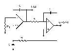
quadrature_oscillator.gif

however i only can get a output frequency like 13+MHz,
and the Vp-p is about 100mV.

how can i do to make the output Frequency 1MHz and Vp-p like 3-4.5V?

apreciate if anyone can help.

Best Regards,
Johnson933
 

No, bad math. Those component values get you 1.026 kHz. You can change the capacitor to 47pF and try again. Use a quad op amp and add an amplifier stage to each output to get the amplitude you want.
 
Thank you KJ6EAD.
umm..i tried with different Capacitors already, which is mentioned by you as 47pF.
but i am not able to get the two waveforms,even i changed back to the original what i did test yesterday,
i could not have the two wave forms already..then i change IC chip,still not help..0.0may i know the possible problem?
btw,if i do not have a quad op amp in hand, can i do it with dual op amp?
 

Hi Johnson933,
Question 1: Is R1=R (equal resistors) ?
Question 2: What is the GBW of the opamps used? (Same as KEITH's question).
 
thanks for your reply~
Hi keith1200rs, i am using a LM358(dual op amp.)

Hi LvW, sorry for late reply, i was afk, what i did is, R1 = R, but at the same time,
i did connect a 1Mohms in parallel with R1, cause from the website i searched told me that R1 is needed to be slightly smaller than R.
and the op amp i am using i have the pdf, u all can have a check either it is suitable or not.

i am about to leave work place maybe will reply u all later when i reach home like 1-2 hrs later.

thanks again for your concern. = )
 

Attachments

  • LM358N.pdf
    271.7 KB · Views: 64

i did connect a 1Mohms in parallel with R1, cause from the website i searched told me that R1 is needed to be slightly smaller than R.

Don't do that. It's not a good recommendation. Both time constants should be as equal as possible. Note: Not each recommendation that can be found in the internet is good, helpful and serious.
(Hint: The name of the positive integrator is BTC-integrator. BTC= balanced time constants).

Regarding the opamp used: LM358 is not suited for your purpose and tthe operating frequency (GBW not sufficient).
 
Some application notes that may help: Sine wave generating techniques **broken link removed**,
op amp circuit collection **broken link removed**.
 
LM358 will possibly work at a few kHz. To build a MHz oscillator, you'll need a high speed OP in the multiple ten MHz BW range. It will require a good circuit layout and suitable supply bypassing. I won't suggest it without respective experience in high speed circuit design.
 
Status
Not open for further replies.

Similar threads

Part and Inventory Search

Welcome to EDABoard.com

Sponsor

Back
Top