Continue to Site

Welcome to EDAboard.com

Welcome to our site! EDAboard.com is an international Electronics Discussion Forum focused on EDA software, circuits, schematics, books, theory, papers, asic, pld, 8051, DSP, Network, RF, Analog Design, PCB, Service Manuals... and a whole lot more! To participate you need to register. Registration is free. Click here to register now.

pwm circuit for simple buck converter

Status
Not open for further replies.

octopus dive

Newbie level 5
Joined
Feb 13, 2013
Messages
8
Helped
0
Reputation
0
Reaction score
0
Trophy points
1,281
Activity points
1,332
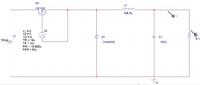
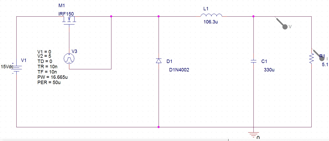
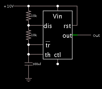
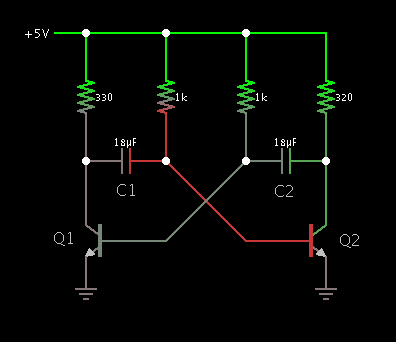
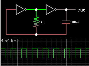
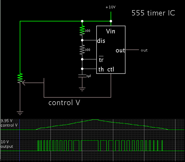
hi..sorry for interruption..I really need help in finding suitable pwm circuit for buck converter with Vin=15v , Vout=5v? here are the schematic diagram of my buck converter's design..hope to hear from u guys soon..thank u..


The PWM is the more complicated part of the design. you need to implement control theory into the loop, something like PID is usually done as opposed to a linear pwm response. to start your transition instead of using that ideal voltage in pulse you should replace it with a comparitor. then you can start flushing out the requirements to get the comparitor to operate correctly, ie compare which node to what reference. there are IC chips that do this in a much more manner that have built in safety options such as current monitor etc to prevent damage to the inductor.
sorry I know im not giving you a specific answer, just pointing you in a direction.
-Pb
 

The buck converter is able to be driven by hysteresis, built around a comparator.


I have not tested this schematic with hardware but it's a start. Adjust values to suit your purposes.

The sense resistor can be a small value, perhaps under 1 ohm. It only needs to show a difference of a tenth of a volt or so, per cycle.
 

To reach a better grasp on the principles, by experimenting with an interactive animated simulator...

Here is a link that will open the falstad.com/circuit website, load my schematic, and run it on your computer. It is similar to my post #3.

https://tinyurl.com/cjwmsxa

Change values by right-clicking on a component, and select Edit.

Try different loads, Vref, hysteresis feedback resistor value, etc.

I do not know for certain how well this circuit can be made to work with hardware.

- - - Updated - - -

-----------------------------------

Here is an interactive simulation where you (the user) can click a switch to start the switch-On cycle.
Then let up to see the switch-Off cycle.

http://tinyurl.com/cnnkhcg

You can see how the duty cycle needs to be timed, as you try to obtain 5V at the load.


i'm really sorry but i don't quite understand about the CLK component in the circuit..it will be hard as i need to build this circuit in hardware form..could u please highlight it in details please by which means its serial name and etc. so that i can find it in any electronic store?
 

CLK is a generic pulse generator. It is the same as V3 in your schematic.
It has to deliver sufficient volt level to turn on the mosfet/transistor.

It might be a 555 timer IC, configured to run in astable mode. There are easy ways to vary its duty cycle.

Or a common astable multivibrator using two transistors, or two logic inverters, etc.


You are undertaking a project which requires that you learn theory at the same time you are building it in hardware. Expect to do a lot of experimenting before you get it right. You may overheat a few components.

You may decide it is easier to use one of the control IC's which are designed to provide PWM to a buck converter (as mentioned in post #2).
 

if i wanted to use the first picture, how can i verify to get duty cycle=0.333??is it by changing the value of resistor or by changing the value of the 10v??
 

change the capacitor value
 

both capacitor or only the top resistor?

- - - Updated - - -

both capacitor or only the top resistor?
 

the +10v is from a dc voltage source? but then what do u mean applying a voltage to ctl pin 5?is it that i need to use another voltage source or how??really for asking..it is just a bit confusing when i try to do this in simulation and applying it to hardware
 

the +10v is from a dc voltage source? but then what do u mean applying a voltage to ctl pin 5?is it that i need to use another voltage source or how??really for asking..it is just a bit confusing when i try to do this in simulation and applying it to hardware

The schematic is to illustrate a concept. Your supply will be 15V. Looking at the scope trace, it implies that you will obtain 33% duty cycle by applying a volt level to CTL pin 5 which is 1/3 of the supply V.

There are also ways to adjust duty cycle which hook up to the resistor/capacitor network (at the discharge/ trigger/ threshold pins). You may decide to use one of those, if you think it will be easier.

I suppose your output needs to be regulated to 5V? In that case you will take a sense voltage from your output, and use that to apply the correct volt level to CTL pin 5. To this it probably will first need to be shifted/ inverted/ amplified/ attenuated. An op amp might be handy to do that.

Here is a link listing some projects which use a 555 IC to control a switched-coil power supply:

http://www.next.gr/power-supplies/switch-mode/555-timer-as-a-switch-mode-power-supply-l4693.html
 

Status
Not open for further replies.

Similar threads

Part and Inventory Search

Welcome to EDABoard.com

Sponsor

Back
Top