Continue to Site

Welcome to EDAboard.com

Welcome to our site! EDAboard.com is an international Electronics Discussion Forum focused on EDA software, circuits, schematics, books, theory, papers, asic, pld, 8051, DSP, Network, RF, Analog Design, PCB, Service Manuals... and a whole lot more! To participate you need to register. Registration is free. Click here to register now.

Puzzled by a stepper motor

Status
Not open for further replies.

bobsun

Full Member level 2
Joined
Mar 5, 2011
Messages
120
Helped
0
Reputation
0
Reaction score
0
Trophy points
1,296
Activity points
2,239
Hi,

I would like to ask a question on stepper motor.

19_1317573926.png


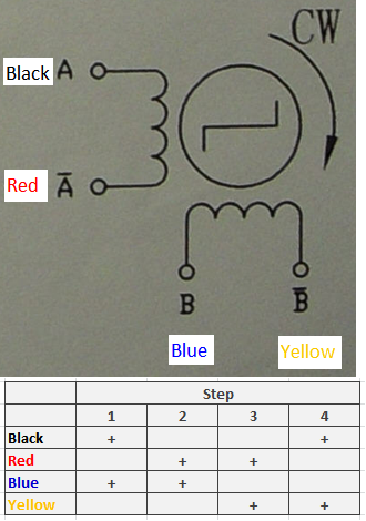
I have recently bought a new permanent magnet stepper motor. According to its datasheet, it requires two poles to be driven simultaneously to rotate.

I was not able to figure out its internal magnet and electric pole structure. Could anyone infer it out?


Bob
 

  • Like
Reactions: bobsun

    bobsun

    Points: 2
    Helpful Answer Positive Rating
The following is one of the most comprehensive tutorials on stepper motors available online:

**broken link removed**

Do you have the datasheet for your stepper motor? What is the make and model?

BigDog
 
  • Like
Reactions: bobsun

    bobsun

    Points: 2
    Helpful Answer Positive Rating
Alex,

steppermotor_singlecoil.gifsteppermotor_doublecoil.gif

If you look at the two examples of "Half stepping" in the "How Stepper Motors Work" link, either for one-coil or two-coil excitation, through the steps the number of poles that are being excited is are not constant. It changes in a pattern like "1, 2, 1, 2".

But for the motor I encountered, the datasheet requires at all four steps driving two poles, although with direction change. I was not able to figure out its internal structure.

Is there any one help able to dissect it by analyzing?

Bob
 

prmurthy,

In you linked PDF I found the following example:

steppermotor_normal_fullstep.png

I don't under how "Normal full step" in the example works. Is there any animation for that?

Bob
 

It's a simple full step pulse scheme, which can be driven either to one (called "wave drive" in your scheme) or two coils ("normal" full step). Driving both coils results in slightly lower copper losses due to a higher duty cycle. If you sketch the flux vector, it's still rotated by 90 degree (electrical) steps.
 
  • Like
Reactions: bobsun

    bobsun

    Points: 2
    Helpful Answer Positive Rating
See

You are using

Terminal 1a + + - - + + - - + + - - + + - -
Terminal 1b - - + + - - + + - - + + - - + +
Terminal 2a - + + - - + + - - + + - - + + -
Terminal 2b + - - + + - - + + - - + + - - +

You change the polarity of one coil in each step, this is full step drive

Alex
 
  • Like
Reactions: bobsun

    bobsun

    Points: 2
    Helpful Answer Positive Rating
prmurthy,

In you linked PDF I found the following example:

View attachment 62154

I don't under how "Normal full step" in the example works. Is there any animation for that?

Bob

Bob please co-relate with your image that yo have provided in the begning. Both are same. FvM has explained.
 
  • Like
Reactions: bobsun

    bobsun

    Points: 2
    Helpful Answer Positive Rating
FvM,

I got it, thanks.

Bob

---------- Post added at 22:44 ---------- Previous post was at 22:43 ----------

purmurthy,

I could run it with full-step now, thanks.

Bob
 

How are you driving your stepper motor, with MCU or dedicated driver module?

BigDog
 
  • Like
Reactions: bobsun

    bobsun

    Points: 2
    Helpful Answer Positive Rating
bigdogguru,

Sorry for my delayed response.

I am driving motor with a MCU, and is in full-step mode. There is a L298N H-bridge to control the current direction.

Bob
 

  • Like
Reactions: bobsun

    bobsun

    Points: 2
    Helpful Answer Positive Rating
bigdogguru,

Thanks for the links. I will have a look at them.

Bob
 

Status
Not open for further replies.

Similar threads

Part and Inventory Search

Welcome to EDABoard.com

Sponsor

Back
Top