Continue to Site

Welcome to EDAboard.com

Welcome to our site! EDAboard.com is an international Electronics Discussion Forum focused on EDA software, circuits, schematics, books, theory, papers, asic, pld, 8051, DSP, Network, RF, Analog Design, PCB, Service Manuals... and a whole lot more! To participate you need to register. Registration is free. Click here to register now.

purpose of the capacitor

Status
Not open for further replies.

Manchested

Member level 5
Joined
Apr 25, 2011
Messages
87
Helped
1
Reputation
2
Reaction score
1
Trophy points
8
Activity points
0
is there any purpose for a capcitor connected between the postive voltage rail(+5V) and negative voltage rail (-5V)?
 

This is a decoupling capacitor, used to protect DC Devices from noise or ripples. You could find tones of articles about it, just google search for "decoupling capacitor". Here is the article of Wikipedia:
 

i thought decoupling capacitors are connected between power rail and ground?
 

i thought decoupling capacitors are connected between power rail and ground?
The pins should not necessarily be +5v and GND, it can be +ve and -ve supply also.
Also, can you post the circuit in which you have seen this ?
 

in which circuit you are using it pleas upload the circuit .in practical case the capcitor block dc and allow to flow ac.
 

I think if a capacitor has equal potential on both terminals it will not do anything because one terminal of the capacitor must be at ground potential in order charge.
 

I think if a capacitor has equal potential on both terminals it will not do anything ...
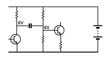
Firstly, the first post said "a capcitor (sic) connected between the postive voltage rail ... and negative voltage rail ..."

Secondly, consider the following skeleton circuit.

skeletoncircuit.gif


The capacitor will most cetainly do something. It will transfer any variation from the collector voltage of the first transistor to the base of the second.

... one terminal of (a) capacitor must be at ground potential in order charge.
Why do you think that?

The terminals of a capacitor must have a voltage across them in order to charge. That voltage difference can be from anywhere.
"Ground" has nothing to do with it.
 

the decoupling capacitor is connected between the positive rails and ground. this is done in order to remove the noise offsets in devices(and to couple the devices in synchronous to each other in a single chip). this is mainly employed in chip fabrications , wherever the spaces are available..for ex: in cadence spectre environment we use these decoupling capacitors.:!:
 

From ground potential I mean there must be a potential difference greater than 0 in order to charge a Capacitor. Yes you right it doesn't matter whether one terminal is ground or not if it is creating potential. for example in electrostatic the potential difference of both charges will be same
0 and +5 = +5
-1 and +6 = +5
-3 and +8 = +5
but if both are equal and opposite then their potential will be 0.
-5 and +5 = 0

If we connect equal and opposite charges through any component there will be no flow of electrons.
 

Status
Not open for further replies.

Part and Inventory Search

Welcome to EDABoard.com

Sponsor

Back
Top