Continue to Site

Welcome to EDAboard.com

Welcome to our site! EDAboard.com is an international Electronics Discussion Forum focused on EDA software, circuits, schematics, books, theory, papers, asic, pld, 8051, DSP, Network, RF, Analog Design, PCB, Service Manuals... and a whole lot more! To participate you need to register. Registration is free. Click here to register now.

Purpose of Balanced Line In "Lift" Switch ?

Status
Not open for further replies.

Zaaappp

Newbie level 6
Joined
Mar 26, 2016
Messages
13
Helped
2
Reputation
4
Reaction score
2
Trophy points
3
Location
Florida USA
Activity points
162
Hi All,

I'm assuming the lift sw (when open) causes the "ground" to float some (thus the name "Lift"), and/or decouple a (possible) DC component in the signal?

Can anyone explain what's really going on here, e.g. attempting to eliminate ground loops, and when / why it would be needed ?
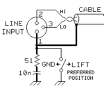
BalanceLineIn-LiftSW.png

- excerpt from a Jensen-Transformer.com https://jensen-transformers.com schematic.

thanks!
- Howard in Florida
 
Last edited by a moderator:
With the 51 ohms and 10kF its only providing a "ground" to RF frequencies not AC hum. I can only guess its to decouple the screen when you use this kit on a MF/VHF transmitting site.
Frank
 
  • Like
Reactions: Zaaappp

    Zaaappp

    Points: 2
    Helpful Answer Positive Rating
I think the schematic is incomplete so that the idea behind the lift switch can't be easily understood.

The question is already confusing the problem. I read the problem differently. A balanced audio line is taken as granted, e.g. a balanced microphone or line level input of an amplifier or mixing desk. ("line input" suggests line level). It uses a 3-pole standard XLR socket, the cable screen terminal can be disconnected from local ground ("lifted"). If the cable connects to a balanced output, a ground loop through the cable screen (lift switch closed) won't matter in a first order. But the source could be also single ended, e.g. an audio effect using tip&sleeve connector at the other end. In this case, ground loop currents will be injected into the audio signal due to unavoidable cable resistance. Opening the lift switch breaks the ground loop.
 

Thanks for the replies. OK, sorry if that was confusing … thought it would be clear from "line in" that this is audio.

That balanced-line microphone cable goes straight into the primary of a Jensen (audio) transformer ( I'm assuming it has an input Z of about 600 Ω, secondary goes straight into a standard audio preamp. [I don't think Jensen wants their full schematic's as you have to have been granted access to them. Was hoping partial info would suffice.]

I think that cable could be upwards of several hundred feet as the whole thing is intended as part of a sound mixing system.

Is that enough info to clarify?
 

A problem can sometimes arise, when something is "grounded" to the building supply ground at one point, and a very remote piece of equipment is also "grounded" somewhere else. There may be a very noisy few volts difference between these two "grounds".

Now a truly balanced system, especially with a floating transformer winding at least at one end should be fairly noise immune.
But some surprisingly high current may flow through the cable braid driven by the difference in ground potentials at each end.

Strictly speaking a cable shield should only be grounded at one end only, to prevent this problem. So to avoid a ground conflict, the ground to cable shield connection should be broken (at either end will work).

But at radio frequencies, the screen itself can act as a long antenna and develop quite a high voltage at the ungrounded end. So to damp out and shunt some of this induced RF, a low value capacitor plus resistor can sometimes be helpful.

In the case of a microphone, the screen is usually attached both to the microphone shell, and solidly grounded at the amplifier input.

But what if the microphone is bolted through a steel panel somewhere remote, and the steel panel connected to mains earth ?
In that case you must break the ground at one end, and that appears to be the function of this magic switch.
 
  • Like
Reactions: Zaaappp

    Zaaappp

    Points: 2
    Helpful Answer Positive Rating
Despite of risking ground loops, the screen of balances audio lines is usually grounded at both sides. We can rely on a balanced design that prevents possible ground loop currents to be injected into the signal path. In special cases, e.g. a large distributed PA system, grounds may be disconnected purposely if required.

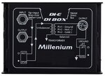
For this reason, it's unusual to have regular ground lift switches at line or microphone inputs of amplifiers or mixing consoles. But they are pretty standard for DI (direct insert) boxes used to connect guitars, keyboards or amplifier outputs to the mixing console.

DI.jpg
 
Excellent replies, much appreciated! Your explanations make sense - and FvM's direct box image cinches it as I believe the circuit is used for live, musical stage gear.

Warpspeed said:
So to damp out and shunt some of this induced RF, a low value capacitor plus resistor

Is the frequency of that shunt as simple as an RC (e.g. that 51Ω x 10ηF) ? Or would the H of the cable have to be included / guestimated. … sort of a wide-band notch filter? (This stuff seems pretty arcane :bang: )

- H
 

Status
Not open for further replies.

Similar threads

Part and Inventory Search

Welcome to EDABoard.com

Sponsor

Back
Top