Continue to Site

Welcome to EDAboard.com

Welcome to our site! EDAboard.com is an international Electronics Discussion Forum focused on EDA software, circuits, schematics, books, theory, papers, asic, pld, 8051, DSP, Network, RF, Analog Design, PCB, Service Manuals... and a whole lot more! To participate you need to register. Registration is free. Click here to register now.

Pulse Current Protection

Status
Not open for further replies.

sabu31

Advanced Member level 1
Joined
Jan 28, 2011
Messages
446
Helped
12
Reputation
24
Reaction score
13
Trophy points
1,298
Activity points
5,153
Dear All,

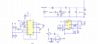
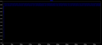
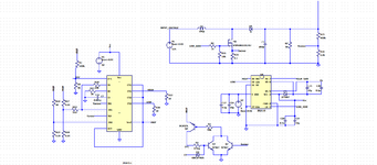
I am trying to implement pulse over current in a boost converter controlled by TL 494. The recommended circuit is given in attached of TI . However, in this case, the output to the Dead time control (DTC) is always high resulting in no pulse being generated. What is wrong in my implementation.
 

Attachments

  • TL494-PULSECURRENT.pdf
    28.2 KB · Views: 119
  • TL494_PULSE_CURRENT.png
    TL494_PULSE_CURRENT.png
    53.2 KB · Views: 92

The given circuit doesn't show complete DTC pin wiring. There must be an additional pull-down resistor or voltage divider, depending on the intended deadtime in normal operation.
 

Thanks FvM for the reply. I have updated the circuit to include resistor divider. However, now also the voltage at DTC point is around 5V.
 

Attachments

  • TL494_DTC_waveform.png
    TL494_DTC_waveform.png
    26.5 KB · Views: 88
  • TL494_PULSE_UPDATE.png
    TL494_PULSE_UPDATE.png
    50.1 KB · Views: 87

Look at the simulation waveforms to understand why the circuit isn't working as expected.
Yes DTC input is 5V which is leading to pulse being stopped.
However, as per the transistor circuit, it there is no base drive, Q2. The voltage at DTC should decay to low levels. This is not happening. Is there something else which i am missing
 

I believe to properly do peak current limiting with TL494 you have to replace the cap into the DTC pin with your sense resistor. (though i need to reread TL494 datasheet, but i am loath to do this as TL494 is a stinker of a chip!)
You are using the internal opamp for current limiting, and you should not do that.

But better still, use a proper current mode control chip like UCC28C43 or similar.
TL494 is a dreadful chip....only useful for old fashioned voltage mode controlled power supplies.
I have not put any capacitor in the DTC circuit which is shown. Though I think capacitor is required for soft starting. Is there any issue due to the Resistors R3 , R2 or in selection of transistors.
 

..well, the Q1, Q2 cct looks like some kind of latch...but using the dodgy vbe of a bjt, not adviseable.
Also, your gate drive is only 5v, and there is no need to use a half bridge driver to drive a boost.
Can you google "current mode control with TL494"......i did, but didnt find anything, but some search like that should reveal
--- Updated ---

Also, i dont see an integrator in your cct (integrator error amplifier)
 

Status
Not open for further replies.

Similar threads

Part and Inventory Search

Welcome to EDABoard.com

Sponsor

Back
Top