Continue to Site

Welcome to EDAboard.com

Welcome to our site! EDAboard.com is an international Electronics Discussion Forum focused on EDA software, circuits, schematics, books, theory, papers, asic, pld, 8051, DSP, Network, RF, Analog Design, PCB, Service Manuals... and a whole lot more! To participate you need to register. Registration is free. Click here to register now.

PSFB output voltage stabilization issue

Status
Not open for further replies.

Porsche

Member level 1
Joined
Jul 16, 2021
Messages
32
Helped
1
Reputation
2
Reaction score
1
Trophy points
8
Activity points
523
Hello everyone! I got some issues with PSFB output voltage stabilization. I used UCC3895 datasheet as reference for moderator action: removed link to external file server.
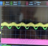
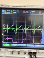
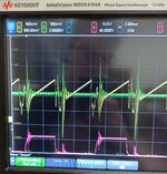
The problem occurs when converter starts to stabilize output voltage. The output voltage is somehow stable, but stabilization occurs at audible frequency so I can hear crackle and unpleasant noise. Waveforms shows that stabilization occurs in a few beats then EAP voltage hits no-load comparator threshold and disables the output. Then EAP voltage rises, PWM enables and everything is repeated again. I tried to put C26 in wide capacitance range (100p up to 0.1u) and this is didn't help much. Did anybody faced a similar problem, what is proper way to make it stable?
Please look at the waveforms and schematic. Yellow – voltage on EAP pin, green and pink is Vgs voltage of QA and QD mosfets. Load is ~6R:
1627292804175.jpg

1627294704092.jpg

1627292804178.jpg


fb2.JPG

fb1.JPG
 
Last edited by a moderator:

Porsche, it's probably worth your time to take a couple steps back and examine your feedback loop more closely. I would disable the power stage completely, and manually apply Vout with a variable DC source. Slowly sweep Vout around your desired setpoint, and observe the change on the EAP pin. You should see that it's very touchy since the TL431 circuit acts as an PI (type II) compensator.

Then short out C26 so that you're left with a simple proportional controller. The DC gain of this circuit is now the same as the high frequency gain of the original circuit (Also the setpoint of Vout will change due to the additional DC path, just ignore that for now). You should take note of how much swing on Vout is required to cause the EAP voltage to saturate high and low. Should be +/-10-25% of your nominal Vout. If not, your gain is way too high. Probably the optocoupler like Easy Peasy mentioned.

If everything's fine so far, then put C26 back in but with a much larger value (like 150nF). Now loop will be very slow, but at least it should be stable. If that works out then we can try properly adjusting from there.
 

You can see the Vea swing full rail in just a few switching cycles in the information above ( post #14, 2nd image from left at lower ) - showing the gain is too high - so either the loop must be adjusted - or the opto - or both.
 

1627953278095.png

Notice how for 5mA in the LED, the Ic can be 4 to 13mA for the A or B version - quite the variation

2.5 - 30mA for the un-binned .....
 

AFAIK all optocouplers should be expected to have wide tolerance, factor of two or three doesn't sound abnormal. Which is why I don't use them when I really want to optimize loop gain. But I'm guessing the loop gain here is high by more like a factor of ten.
 

HCPL4503 and the associated range have narrow and low gain - and are used in millions of telecom supplies as they are stable ....
 

    mtwieg

    Points: 2
    Helpful Answer Positive Rating
So, the best I could find for now is TLP785 YE which CTR ranges from 50 up to 150%. I have also decreased R22 2.2k down to 1k to even more reduce gain (btw, is it a valid way...?). With C26 at 330 nF I could finally make it stabile under a certain (300-350W) load. But if I decrease load to around 200-250W noise is coming back. Does this mean it is still too much gain?
Here is waveform when the noise comes back:
when the sound comes back.jpg

And I also tried to put C26 as Easy peasy said «2 x 470nF in series, and place 4k7 across one of them» and it made situation a little bit better. So, I continued increase C26 and around 1uF I could it make stable even at ~200W load but only if I decrease output capacitors down to 1000uF, with default 6000uF it can’t be stable at ~200W.

R53 etc ( R turn on ) should be closer to 15 ohms
Am I missing something, but how can it affect feedback loop?
it is common practise to put resistors in series with the associated diodes
You mean put 10-22 Ohm in series with D9 and D10?
R43 needs to be at least 1W rated - 20mA x 28V = 560mW
Yup, this is my mistake, thanks. I replaced it with a leaded resistor, should work for now.

Porsche, it's probably worth your time to take a couple steps back and examine your feedback loop more closely.
Hello, mtwieg! Thank you for telling about this interesting method of testing feedback loop. I tried it just as you said and here is some data:
R22 is 1k and C26 150nF with TLP785YE It is very touchy, just as you said!
VoutVeap
42.625
42.644.8
42.663.7
42.681.3
42.700.4
42.760.25

R22 is 1k and C26 shorted with TLP785YE
VoutVeap
5.95
6.714.9
7.544.8
8.384.58
9.214.29
10.043.9
11.703.2
12.542.84
13.372.44
14.621.8
15.031.6
25.40.2
It is more like +-50% deviation, not 10 or 20, does this mean gain is too low or too high? I am little bit confused now…

And one more question, while this thing is stable (without any noise), when i increasing the load up to 700W or more sawtooth become distorted (please see waveform). Is it okay, or again I did something wrong?
High current & low current (Green is EAP)
High current.jpg1628070997901.jpg
 
Last edited by a moderator:

you need to slow the control loop further, you still have insufficient slope comp, did you fit the film/foil caps across the totem poles?
 

Also, this:
1628120406962.png


is 8.33mS period, I assume you have a 60Hz supply? this is the ripple on the input ... see for yourself .....
 

I am sorry for delayed answer. When I was messing around with feedback loop QC somehow popped. There was really unstable situation accompanied with loud crackle and then QC MOSFET just gone. I don’t really know how it could possibly happen since my CS pin is connected to the CST… Maybe Tx could saturate during unstable feedback operation but why then CS didn’t trip… idk.

Anyway, I replaced QC with a new one and added everything you mentioned above. Soon I will provide new waveforms.
did you fit the film/foil caps across the totem poles?
Yes, it is there now. 220nF. Fitted it right at the MOSFETs pins.
you need to slow the control loop further
I am sorry for stupidity of following question but Is the C26 is only tool I need to use to tune speed of the control loop? I mean there is R41 @ 220R as you told me. Should I leave it there for now?
is 8.33mS period, I assume you have a 60Hz supply? this is the ripple on the input ... see for yourself .....
I don’t think so. First of all because I use only SMPS TDK-Lambda GEN 600 to power up my circuit. And the second thing is we have 50 Hz power outlet here in my country. So, it has nothing to do with 60Hz of power supply ripple.
 

It will be interesting to see the output of the DC source ( GEN 600 ) when it is all going again - RFI from your converter could be affecting it.

How much current can it supply ? @ 250VDC ?
 

    mtwieg

    Points: 2
    Helpful Answer Positive Rating
HCPL4503 and the associated range have narrow and low gain - and are used in millions of telecom supplies as they are stable ....
Looking at the datasheet, it gives a CTR range of 19-50%, but it isn't clear how much of that is due to temperature variation and how much is process variation. I'm assuming it's mostly from temperature, but I wish they included a histogram or something. Anyways thanks I'll keep this part in mind.
 

It’s seems that 220nF at the totem poles gave a significant improvement. First of all, noisy sound is completely gone (or become almost indistinguishable) from 200 up to 700W range even with a 100nF C26 and converter regulating the output. But still at load lvl around 315W and below strange «sinewave» behavior remained.

Here is waveform: Pink is Vin from GEN600 at the input connector (AC coupled!) Green is Veap and Yellow is the RAMP pin voltage. Total input power is 315W
350x09.png

Everything becomes nice and clean from 350W and higher:
350x1.png

There is one more strange thing. When everything works fine and converter stabilize, the RAMP sawtooth looks kind of strange. Look at that knee, is it how it supposed to be? (I measured it using spring type thing, should be less noise time)
ramp.png

But lower load range is still unstable. With 2W of output load converter becomes a "clock" generator with frequency of 1-30Hz (depends of Vin, C26) it is trying to stabilize at that frequency and you can clearly hear these ticks.

And also I added 1uF in series with L1 in safety purpose, to prevent Tx saturation, it shouldn't ruin anything I think.
How much current can it supply ? @ 250VDC ?
GEN 600-8.5-3P400 can supply 8.5A average current @250VDC. But I set current limit around 2.5A. Increasing of this threshold (up to 6-7A average) didn’t affect at converter so I dont think PSU hits CC mode.
 

you power source is hardly a true voltage source is it ? with about 1/2 a volt peak of ripple at 315W, of course we don't know what the voltage was set to for that test ?

But any decent bench power supply should be heaps better than that for 120Hz ripple - hence likely being affected by the RFI from your converter.
 

you power source is hardly a true voltage source is it ? with about 1/2 a volt peak of ripple at 315W, of course we don't know what the voltage was set to for that test ?
I set Vout to 350V. What is the source of RFI in my converter? MOSFETs? Should i increase turn-on time?
 

Status
Not open for further replies.

Similar threads

Part and Inventory Search

Welcome to EDABoard.com

Sponsor

Back
Top