pxidr
Newbie level 5
Hi everyone,
A bit new here, seeking help for my issue after many attempts to solve the problem myself...
I'm currently developping a 100kHz, 24kW PSFB for an EV charger, using a full-bridge SiC MOSFET at the input (700VDC nominal), a custom-made planar transformer, and full-bridge SiC diode rectification at the output (4x2 STPSC30H12CWL arranged in parallel for current handling), the goal of the design is outputting a variable 50-500VDC at 64ADC max.
My output inductor is 33uH and my output capacitance is 200µF, using 4x50µF low ESR film caps (TDK B32776Z5506K000).
I'm currently testing my PSFB on a 300VDC lab power supply and a 2kW resistive load, voltage and current regulation at the output are fine.
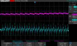
At 110VDC output, 10ADC, my voltage ripple is acceptable (about 1,26V pk-pk), but my current ripple is way too high (776mA pk-pk).
I'm unable to resorb this current ripple. The weird thing is that current ripple doesn't increase if I increase the load, it is pretty constant at 2A, 5A, 10A etc.
Any suggestions for filtering out that current ripple ?

A bit new here, seeking help for my issue after many attempts to solve the problem myself...
I'm currently developping a 100kHz, 24kW PSFB for an EV charger, using a full-bridge SiC MOSFET at the input (700VDC nominal), a custom-made planar transformer, and full-bridge SiC diode rectification at the output (4x2 STPSC30H12CWL arranged in parallel for current handling), the goal of the design is outputting a variable 50-500VDC at 64ADC max.
My output inductor is 33uH and my output capacitance is 200µF, using 4x50µF low ESR film caps (TDK B32776Z5506K000).
I'm currently testing my PSFB on a 300VDC lab power supply and a 2kW resistive load, voltage and current regulation at the output are fine.
At 110VDC output, 10ADC, my voltage ripple is acceptable (about 1,26V pk-pk), but my current ripple is way too high (776mA pk-pk).
I'm unable to resorb this current ripple. The weird thing is that current ripple doesn't increase if I increase the load, it is pretty constant at 2A, 5A, 10A etc.
Any suggestions for filtering out that current ripple ?
Last edited: