Continue to Site

Welcome to EDAboard.com

Welcome to our site! EDAboard.com is an international Electronics Discussion Forum focused on EDA software, circuits, schematics, books, theory, papers, asic, pld, 8051, DSP, Network, RF, Analog Design, PCB, Service Manuals... and a whole lot more! To participate you need to register. Registration is free. Click here to register now.

PSFB - Current waveform explanation?

Status
Not open for further replies.

Magnethicc

Member level 2
Joined
Feb 7, 2022
Messages
48
Helped
1
Reputation
2
Reaction score
6
Trophy points
8
Activity points
646
Can someone explain why does the primary current of a PSFB has the following waveform:
1649235552995.png


at first current ramps up (magnetizing + reflected output inductor current).
At the start of the phase in which current is circulating there is a dip in the current waveform.
My question is why there is a dip? where did it came from and where did it go?


The article states that the reason for this dip is due to several capacitances around the transformer (for example snubbers and rectifier junction capacitances) that steal current to charge/discharge - if this is the case why wont the current will ramp back up once the charging/discharging is done?
 

Attachments

  • 1649235530728.png
    1649235530728.png
    17.1 KB · Views: 119
Last edited:

hi,
Provide NP/NS and Lout and frequency and ill sim it and try and recreate it for you, then tell what it is.
Attached is sim i will modify to you.
 

Attachments

  • PSFB_5500W.zip
    4.4 KB · Views: 111

Primary 36 Turns (Lmeg = 8.7mH).
Secondary 26 Turns.
Switching frequency = 60kHz (Clock = 120kHz).
Lout = 195uH.
Ls = 3.4uH (Series Inductance with the primary).
Vin = 620VDC.
Vout = 290V.
Iout = 5A.

1649249580452.png

Red - 1/2 of primary current (incidentally took the plot with Full BW on that channel that is the reason for the mismatch)

Green - 1/2 of primary current

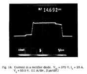
Orange - Current in rectifier diode (equivalent to D5 on the simulation)

Purple - Current in the rectifier diode below it (equivalent to D3 in the simulation)
 

Hi,
the attached is your PSFB in the LTspice simulator.....i had to increase your output inductor otherwise i got subharmonic oscillation.
Yes the waveforms dont look like your primary.....but i will experiment by increasing the capacitance across the fets and snubber capacitances etc etc...but feel free to do some phorensic work yourself...together we will bust the bad waveform.....

I assumed you used a full bridge output?
--- Updated ---

....ahaaa....i have some detective work done.....i included the leakage inductance in the transformer as well as your external "leakage" inductor....and i am getting your "dip down" bit......so the culprit appears to be leakage inductance....did you sandwich wind the txfmr....?..

...as attached is the LTspice simulaiton including the guilty leakage inductance
 

Attachments

  • PSFB_620V TO 290V 5A.zip
    4.4 KB · Views: 113
  • PSFB_620V TO 290V 5A_llk.zip
    4.4 KB · Views: 115
Last edited:

Thank you cupoftea!
The culprit has been found to be the capacitances of the rectifier diodes and the leakage inductances.

At the moment of switching between power phase to freewheeling phase the capacitances of the diodes (the ones who did not conduct during the power phase) needs to be discharged since the transformer is practically shorted in the primary. this discharge current is stolen away from the transformer since the output inductor current is the load current (Assuming output inductor has a much larger energy than the leakage inductances) - this will force a downward step from all current paths (transformer, conducting diode) such that enough current is available for the discharge of the rectifier diodes.

* if the total leakage inductance seen from the secondary is large enough- it will resist the downward step and it will be smaller.

once discharge is over the leakage inductances will resist their change in the current so this discharge current will now flow through the diodes which did not conduct before.

please note - there are several other reason to get the same waveform and downward step but those are not discussed here.
 
Status
Not open for further replies.

Similar threads

Part and Inventory Search

Welcome to EDABoard.com

Sponsor

Back
Top