Continue to Site

Welcome to EDAboard.com

Welcome to our site! EDAboard.com is an international Electronics Discussion Forum focused on EDA software, circuits, schematics, books, theory, papers, asic, pld, 8051, DSP, Network, RF, Analog Design, PCB, Service Manuals... and a whole lot more! To participate you need to register. Registration is free. Click here to register now.

[SOLVED] Project to replace CY7C64613 in the ICD2

Status
Not open for further replies.
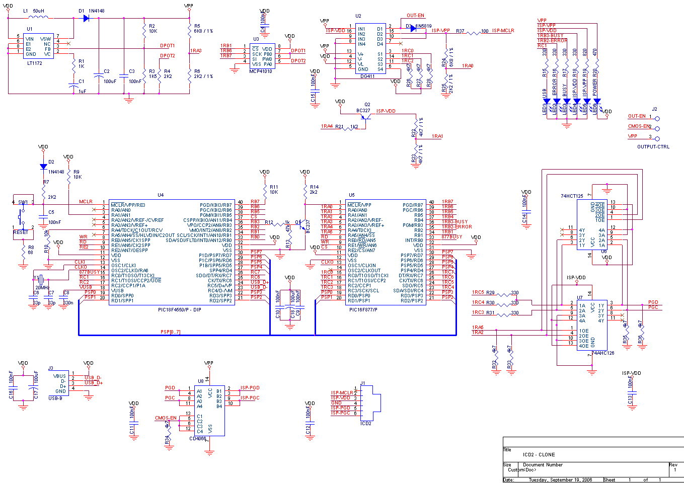
yea, i stablished comunicatión now, (simply using an "A" PIC) the hardware is exactly the same, but now, wich points must i mesure?

Added after 1 minutes:

(extra: i just damaged 2 4550 tring to make the brener8 pic burner... so i have only 1 4550 now... :(:cry:)
 

Because your clon communicate with PC I suppose that yours +5V supply is ok. Check the part of icd2 that provide you with +13V. If it is OK, then check voltage deviders which are connected to RA0, RA1 and RA3 of 877A.
 

exactly the same thing hapeens to me withthe brener8 USB pic burner, there is not voltages at ICSP conector, sometimes the measuret voltajes are wrong, sometimes there is not reads... can be the type of transistors that i use? they are BC547 & BC557s. I don´´t use the USB to Vdd coil, i use 22pF capacitor for the cristals... Come of that could be the problem?????
 

roykyn said:
is Project to replace CY7C64613 in the ICD2 ready and working if it does i ll start working on it
plz give me the sch-pic-pcb of it
Read the entire topic, and you will find anwers for your questions.
 

I don't know what is "brener8 USB pic burner" and why you insist with that. We will go step by step because i think you don't understand me well. Tell me how do you provide 13V on your board? What is "USB to Vdd coil"?
 

predrage said:
I don't know what is "brener8 USB pic burner" and why you insist with that. We will go step by step because i think you don't understand me well. Tell me how do you provide 13V on your board? What is "USB to Vdd coil"?

... the brener8 USB pic burner is a german PIC programer via USB 2, it has suport for almost of PICs at
Code:
it was only a comment, because im making it beside this ICD2 project and it uses PIC18F4550 (2550) too, so is just a coment...
Im using the SCH&PCB provided by arts, so i´m using the MC34063 chip to generate the Vpp. The "USB to Vdd coil" is the coil that goes from +5v of the USB connector to +5v or Vdd of the circuitry of the ICD2 clone (Vdd of the chips, leds, resistors, etc) but i´m do not using it ( i just put a straight cable..like my all other working PIC-USB projects), i´m now measuring the voltajes on the specific point (voltajes dividers) but apears to be right... so maybe the problem could be the transistors, i´ll go to check them and after i will continue comenting here. Thanks again for the help.[/code]

Added after 1 hours 23 minutes:

Hi, after i´m checking and rechecking and rechecking and..., i finally pass all the self-test:
target Vdd 4.96
target Vpp 12.78
MPLAB ICD 2 Vpp 12.86

There was a bad transistor as i supossed (Jodidos venderoes mexicanos...) so now i have a correct conection, aparently a working ICD2, but now i have this:
Auto-connect not enabled - Not connecting (Try enabling auto-connect on the ICD2 settings pages.)
Connecting to MPLAB ICD 2
...Connected
Setting Vdd source to MPLAB ICD 2
ICDWarn0020: Invalid target device id (expected=0x47, read=0x0)
...Reading ICD Product ID
Running ICD Self Test
...Passed
MPLAB ICD 2 Ready
Connecting to MPLAB ICD 2
...Connected
Setting Vdd source to MPLAB ICD 2
Target Device PIC16F872 found, revision = Rev 0x2
...Reading ICD Product ID
Running ICD Self Test
...Passed
MPLAB ICD 2 Ready
ICDWarn0015: Program memory has changed since last program operation? Continue with Debug operation?
Stepping Target
ICD0083: Debug: Unable to enter debug mode. Please double click this message for more information.
MPLAB ICD 2 Ready
Downloading Operating System
Connecting to MPLAB ICD 2
...Connected

how i must connect the icd2 to target? vía PGD and PGC? the target pic, which conections must have to? it recognizes almost PICs that i have (877,877a,872,876a,628, 18f4550, 18f2550, etc), also it indicates a right programmed device:
Auto-connect not enabled - Not connecting (Try enabling auto-connect on the ICD2 settings pages.)
Connecting to MPLAB ICD 2
...Connected
Setting Vdd source to MPLAB ICD 2
Target Device PIC16F872 found, revision = Rev 0x2
...Reading ICD Product ID
Running ICD Self Test
...Passed
MPLAB ICD 2 Ready
Programming Target...
...Validating configuration fields
...Erasing Part
...Programming Program Memory (0x0 - 0x81)
Verifying...
...Program Memory
...Verify Succeeded
Programming Configuration Bits
.. Config Memory
Verifying configuration memory...
...Verify Succeeded
...Programming succeeded
17-Sep-2006, 01:43:46

MPLAB ICD 2 Ready

But really, it doesn´t, because the PIC itself in the aplication board don´t work...
so what could now be?

Added after 18 minutes:

... sorry people, but no...
there is some PICs that works in both modes: programmer and debugger.
But some others no, ie pic16f628a, i have some little progrmam for this pic, some of them works in programmer mode, but no in debugger mode and other don´t work in neither mode. Aparently, with the pic16f872, works fine in both modes... why are this problems??
 

Well done gameso. Transistors are next step and you successfully made that step and found error. My clone also don't have "USB to Vdd coil". I think that you can't run debugger with 628a because this device have a small memory and thats why 628a is not supported by MPLAB's debugger. I'm not sure about this but someone will correct me if I'm wrong. Your ICD2 clone is now working fine. Congratulation.
 

WOW, thank you very much. But why it sometimes doesn´t program ? or why in ocassions programs and others no? the debug mode i understand that some pics are unable to debug, but program, why no?
 

On http://www.icd2clone.com there are three different versions of the ICD2. Without reading all 28 pages, can someone give a short hint of which one to choose? Whats differs? The "oldes" pic i will use are 16F877 devices and I'm interessted in programming new 18F and maybe DsPICs/24 devices. The PiCS version seams to be the easiest one. Is an external supply needed for the PiCS version?
 

calgyria said:
On h**p://www.icd2clone.com there are three different versions of the ICD2. Without reading all 28 pages, can someone give a short hint of which one to choose? Whats differs? The "oldes" pic i will use are 16F877 devices and I'm interessted in programming new 18F and maybe DsPICs/24 devices. The PiCS version seams to be the easiest one. Is an external supply needed for the PiCS version?
PiCS version doesn't support DSPIC and 24F devices, because it works only with 5V targets. You need one with level translators on the PGD and PGC, for example this:
Read this topic: for more information.
 

potyo:

Do you have a component list for your updated potyo-2006.09.07.zip version?

Added after 1 hours:

Adding a 3.6V zenner diod att the target MCLR pin, can that be a way to solve that the PiCS version does not support 3.3V targets like DSPIC and 24F?
 

gameoso said:
WOW, thank you very much. But why it sometimes doesn´t program ? or why in ocassions programs and others no? the debug mode i understand that some pics are unable to debug, but program, why no?

Gameoso, try ti use short cable is possible between icd2 and target device and put 100nF capacitors on power line near 877A and 4550.
 

To potyo:

Could you upload pdf version of pcb (or sources from Eagle) for your new version with MC34063 and a part list for this project?

Thanks
 

Gameoso, try ti use short cable is possible between icd2 and target device and put 100nF capacitors on power line near 877A and 4550

I use a 15 cm (5.9 inch) ICSP cable and a 10 cm (3.9 inch) USB cable, and have my ICD 2 board a 0.1uF (100nF) capacitor between power pins of any chip. It is exactly the same PCB of Int Art at page 25 of this toppic.
 

Here are my versions. Partlists, Eagle and pdf files are included. The file sajat.lbr contains every components i have used.

calgyria said:
Adding a 3.6V zenner diod att the target MCLR pin, can that be a way to solve that the PiCS version does not support 3.3V targets like DSPIC and 24F?
No. 16F877 has Schmitt-Trigger inputs on the RC3, RC4 and RC5 pins. Only voltage levels higher than 0.8Vdd (4V) are sensed as a logical high level. Programming and debugging requires 2 way communication.
 

Hi!

Using potyo schematics for 3.3V devices (PIC24 and dsPIC33F) that has output buffers I am modified it to add a DG411. It is the schematics, if anybody thinks that it is incorrect, please notify me...

regards,

togarha
 

I'm so sorry, I think that the image is displayed in the previous post, I try to put the schematics view

regards

2_1158654006.png
 

Doh.. do i really need to wait 14 days until i can get points for my posts so i can download the potyo2.zip file? ...:/

Added after 41 minutes:

Thanks nex. :p
 

in this project,the pic18f4550 chip can be placed by pic18f4450?
 

Status
Not open for further replies.

Similar threads

Part and Inventory Search

Welcome to EDABoard.com

Sponsor

Back
Top