estelle.ros06@live.com
Newbie level 2
- Joined
- Jul 20, 2015
- Messages
- 2
- Helped
- 0
- Reputation
- 0
- Reaction score
- 0
- Trophy points
- 1
- Location
- Pretoria, South Africa
- Activity points
- 39
Hi everyone.
I am new to electronics design and I will really appreciate some guidance with a project I am busy with.
Here is an overview of what I need to achieve:
1. Build a 2Mhz crystal oscillator circuit and filter out the second harmonic (which will be 4Mhz).
2. Build a 4MHz LC VCO circuit using varactors.
3. Use the phase comparator in the PLL chip to phase and frequency lock the two oscillators.
Issues:
1. I have constructed the crystal oscillator circuit, which oscillates at 2MHZ. When connecting the 4MHz bandpass filter, no waveform is seen up on the oscilloscope. Is this due to loading and should a buffer amp be used?
2. The LC oscillator only seems to oscillate at 1.5MHz when built on a pcb, although the component values are simulated for 4MHZ? Must a buffer amp be used as well? I am also not sure if the placement of the varactors is correct to provide tuning range that will be wide enough to ensure a definite lock condition.
3. Will the phase detector section work on the PLL chip if I input the two sine waves (xtal to signal in and lc to PD1)? If not,is there a bjt circuit be used to convert the sines to squares? The opamp circuits are too slow.
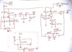
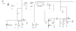
I have attached a hand sketch of my circuit (not the best in the world!)
Thank you in advance
Regards
Estelle
I am new to electronics design and I will really appreciate some guidance with a project I am busy with.
Here is an overview of what I need to achieve:
1. Build a 2Mhz crystal oscillator circuit and filter out the second harmonic (which will be 4Mhz).
2. Build a 4MHz LC VCO circuit using varactors.
3. Use the phase comparator in the PLL chip to phase and frequency lock the two oscillators.
Issues:
1. I have constructed the crystal oscillator circuit, which oscillates at 2MHZ. When connecting the 4MHz bandpass filter, no waveform is seen up on the oscilloscope. Is this due to loading and should a buffer amp be used?
2. The LC oscillator only seems to oscillate at 1.5MHz when built on a pcb, although the component values are simulated for 4MHZ? Must a buffer amp be used as well? I am also not sure if the placement of the varactors is correct to provide tuning range that will be wide enough to ensure a definite lock condition.
3. Will the phase detector section work on the PLL chip if I input the two sine waves (xtal to signal in and lc to PD1)? If not,is there a bjt circuit be used to convert the sines to squares? The opamp circuits are too slow.
I have attached a hand sketch of my circuit (not the best in the world!)
Thank you in advance
Regards
Estelle