Continue to Site

Welcome to EDAboard.com

Welcome to our site! EDAboard.com is an international Electronics Discussion Forum focused on EDA software, circuits, schematics, books, theory, papers, asic, pld, 8051, DSP, Network, RF, Analog Design, PCB, Service Manuals... and a whole lot more! To participate you need to register. Registration is free. Click here to register now.

Project: Casio data-link design (Hacking a protocol)

Status
Not open for further replies.

m.yasser

Newbie level 5
Joined
Jan 27, 2010
Messages
8
Helped
0
Reputation
0
Reaction score
0
Trophy points
1,281
Location
USA
Activity points
1,336
Hi,
The Casio fx-5800P programmable calculator can transfer its data to another fx-5800P calculator serially through 3-pin cable. See figure below.
cross.png
It would be very useful if I can save data to the PC. To do so I have to understand the signal properties and the protocol that the Casio fx-5800P calculators use to communicate with each other. After that I can design a data-link between the calculator and the PC.
I’ll provide information about the communication signals soon.
Regards.
 

As a start I measured the voltage levels of the transmitted signal from the 2.5mm jack. The levels where 0-2.7v, so to connect to PC using a MAX232 based circuits I needed a voltage level of 0-5V. Thus I constructed a simple level converter based on the LM339 comparator which was in my reach. Fig.1 shows the schematic of the level converter, Fig.2 and Fig.3 shows the transmitted signal before and after the level converter.
Fig.1:level converter 300mono.jpg
Fig.2:Mid_TX.jpg
Fig.3:Mid_TX_5V.jpg

The next step is to figure out the protocol that fx5800P use. I needed the baud rate, data bits, parity bits, stop bits to connect the calc to PC HyperTerminal or any other s/w to analyze the outgoing signals using COM port (RS232 serial port). Any suggestions?
 

Attachments

  • level converter 300mono.bmp
    279.4 KB · Views: 92
  • Mid_TX.BMP
    150.1 KB · Views: 89
  • Mid_TX_5V.BMP
    150.1 KB · Views: 87
Last edited:

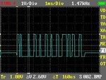
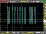
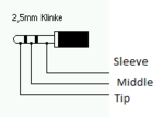
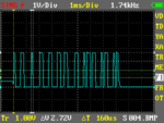
An attempt to find the baud rate, I connected the scope to the tip of the 2.5mm jack 2.5mm jack.png and issue a transmit command for a selected data in the calculator memory. I repeated this action with the probe of the scope connected to the middle of the 2.5mm jack (I really don’t know which one i.e. tip or middle is transmit or receive). Fig.1 below is for the first case, Fig.2 is for the second.
Fig.1:TIP_RX_Press AC.jpg
Fig.2:Mid_RX_Press AC.png
I tried to measure the narrowest pulse width to make an estimate of the baud rate. Fig.1 dt=64 us (micro second), Fig.2 dt=160 us. Fig.1 seems like a strobe of uniform pulses (clock).
Ok, now ill issue a receive command and see what happens.
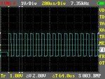
No signal on the tip nor the middle, but when I press cancel (AC button), a signal shows. Fig.3 is for the Tip (2.5mm jack) and Fig.4 is for the middle (2.5mm jack).
It seems that the tip is a clock to the data from the middle. Ok I have to make more measurements
 

Attachments

  • TIP_RX_Press AC.BMP
    150.1 KB · Views: 93

Ok, I'm Back.
TIP_Yellow_Mid_Blue_TX.jpg

This is a 2 channel scope image, the yellow signal is from the Tip of the 2.5mm jack and the blue signal is from the middle (2.5mm Jack). The signals are recorded simultaneously after issuing a transmit command.
It seems that the type of serial communication is Synchronous (RS232 serial COM port in PC uses a different type of signal communication called Asynchronous).
Refer to the figure above; the yellow signal is perhaps a clock for the data signal in blue. Any suggestions? :?:
 
Last edited:

I’m not sure, is this is the right place for this subject? Please inform me.
Thanks.
 

What I see is a clock line and a data line so it resembles I2C protocol

Alex
 

Thank you for your reply,
Yes, I2C was a first conclusion but; I haven’t used it before. I know that it uses s/w addressing instead of h/w. I need some explanation about the I2C protocol and an example will be great. :smile:
Regards.
 

It resembles I2C but is can be using a custom protocol, you can find many articles that explain the I2C protocol using google.
I have only used I2C from AVR a few times so I can't give you much details on the protocol.

Alex
 

Status
Not open for further replies.

Part and Inventory Search

Welcome to EDABoard.com

Sponsor

Back
Top