Continue to Site

Welcome to EDAboard.com

Welcome to our site! EDAboard.com is an international Electronics Discussion Forum focused on EDA software, circuits, schematics, books, theory, papers, asic, pld, 8051, DSP, Network, RF, Analog Design, PCB, Service Manuals... and a whole lot more! To participate you need to register. Registration is free. Click here to register now.

Programming File for 27C64 Eprom

Status
Not open for further replies.

tait 700

Junior Member level 2
Joined
Apr 20, 2012
Messages
20
Helped
0
Reputation
0
Reaction score
0
Trophy points
1,281
Activity points
1,518
Hello,

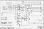
Was wondering if someone that has had some experience in creating a BIN or HEX file suitable for a 27C64 Eprom could point me in the right direction re creating a file that would allow the above Eprom to control the output of its data lines ( D0 - D7 ) so that it will switch the lines either high or Low i.e pull to ground ?

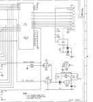
The device is a Remote Channel Change module for a Repeater rack and allows remote selection of channels in the TX and Rx modules by pulling various data lines in the same chip installed in the modules either high or low depending on the channel selected.

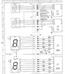
The Eprom in the Channel Change is addressed by a Two digit BCD selectable switch that is paired to a Two digit 7 seg LED that indicates the channel selected and this tells the Eprom which radio Channel to select via a combination of the Data Out lines.

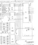
I have a circuit Diagram of the unit and the input to the Eprom is already there with the BCD switching done by a pair of 40175 chips.

I have the Eproms for the TX and RX modules correctly burned with programming files provided by the equipment manufacturer ( Tait ) but i am lost as to how to create a BIN or Hex file from scratch to get the Channel Change Eprom to output the correct switching via its Data out lines.

Apologies for the long first post but if anyone could point me the right direction as to how to create this file i would be most grateful before i wear out my UV Eraser or the Spare Eproms i have been using to test the files :???:

Regards,
 

Now you know why Flash memories are so much easier to use than EPROMs!

If I understand what you want, you have known input lines states and you want to convert them to different output line states by using the EPROM as a look-up table.
It's fairly easy to do, first draw a table (on graph paper or use a spreadsheet) of the input states, these are the EPROM address lines. Then for each input state, write the output state you need, this is what the EPROM should produce on it's data lines. For example:

Input = Output
00000000001000 = 1010101
00000000010000 = 0001001
00000000000110 = 1100011

and so on.

Now convert the numbers to hexadecimal because that's what most EPROM editors use. You might be able to use binary but it's horribly tedious. Remember the 27C64 has 13 address lines so the values on them can be from 0000 to 1FFF but the output is 8 bits so can only go from 00 to FF. Using an EPROM editor, most EPROM programming software has one, at each of the addresses in your input, place the value you want at the output. For example if the input lines were 0000 0100 0110 1100 the address is 046C and you wanted to output 10011011 on the data lines the value to place in 046C would be 9B.
When you have done it for all the input combinations you need, program the chip. HEX and BIN files are just copies of the data in the EPROM, BIN is a raw binary file, just the actual numbers in sequential memory locations, HEX is the same but represented in text format with some extra information about where in the IC the data is to be placed.

Brian.
 
Thank you very much, Brian.

This is exactly what is required, the Thumbwheel switches generate the line states from a Numerical setting (01,02,- 99, etc) and the module displays these on the 7 seg Leds and switches the output lines to match, controlling the Radio Modules.

You have cleared up a lot of my confusion over this and have given me a Good place to start, time to do some serious study.

Cheers,

Tait 700.
 

Thanks Brian,

I am still having trouble getting a Correct Eprom image that will work correctly combining the Channel change module and the radio Module.

The radio module Eprom is working correctly as i can manually select the Channels via the 8 pin Dip switch and they follow the Dip Switch codes from the manual.

I am not fluent with Eprom programming and i have probably messed up the conversion from Binary to hex or placed it in the wrong location.

I have the circuit below of the Channel Change module that describes how the output of the Two Pushbutton switches are latched and then feed the 27C64 inputs but i am unsure what input location to start from,

I.E. If i wanted to select 01 on the Pushbutton switches how would that relate to the input states of the Eprom data lines ?

**broken link removed**

I appologise for taking up your time but if you could possibly describe to me how i can work out what the output would be from the 2 Pushbutton switches when they are set to "01" and where its location would be in the Eprom i can maybe work the others out from there.

I would be very grateful for any further assistance you might be able to provide on the above.

Regards,

Tait700
 

Sorry but I get "document not found" when I try that link.

Not sure what you mean by "input states of the Eprom data lines", the data lines are the outputs.

Brian.
 

Sorry Brian, link is not working for me either. I will try and scan a copy of the Circuit Diagram from a hard copy i have.

I worded that badly, not sure now what info i need so that the Eprom can decide which output lines to pull low ( Ground )

Apologies,
 

Attachments

  • Circuit 1a.JPG
    Circuit 1a.JPG
    92 KB · Views: 257
  • Circuit 2.JPG
    Circuit 2.JPG
    84 KB · Views: 214
  • Circuit 3.JPG
    Circuit 3.JPG
    69.6 KB · Views: 259
Last edited:

Got them thanks.

I'm not familiar with the receiver/transmitter but from the diagram I can see how it is supposed to work. The 4093 on the third schematic is periodicaly pulsing the latch signal so the switches are read in. The CD4543 can only decode decimal numbers so I'm guessing the range you can select is from 00 to 99 and is BCD coded.

This means only 100 of the possible 8192 EPROM addresses are actually used and although not marked on the schematic, address lines A8 upward are all unused and tied to ground. Not a very efficient use of the EPROM!

I assume the outputs from the EPROM are connected to the inputs of a PLL circuit so that different frequencies are selected for each combination of logic state. It that is the case, and if the radio is working at the moment, I suggest you note the voltages on the EPROM outputs for each channel number you select. There will probably be a pattern, a certain number of KHz difference in frequency for each increment in number from the EPROM. It would be useful to note this because you may be able to use it to calculate new channel frequencies.

Back to the EPROM data, the actual number on the address lines for each channel number is the binary equivalent of the BCD number. This makes it easy, you can directly use the channel number as the EPROM address and at that address put the binary number of the output you want. For example use EPROM address 0x23 for channel 23, 0x61 for channel 61 and so on. There will be gaps in the contents of the EPROM so don't worry if there are empty addresses you don't use.

Just a thought - if you don't have the new EPROM yet, it would be cheaper to use a small microprocessor to do the job, and it could connect directly to the EPROM socket.

Brian.
 

Thanks Brian,

Have attached a Schematic of the Channel Eprom board that resides in each of the radio Modules. The "External Interface" on the left Hand top is where the Channel Change eprom output connects to directly and you can manually select any of the channels that have been previously programmed via the Tait Software into the radio's own Eprom, via the 8 DIP switches.
I.E Channel 02 ( 446.2000 Mhz ) is selected by moving Dip switches to 11111110 with 0 being the LSB and 1 in position 8 to the left, being MSB.

Thanks for clearing up the mystery of the Address lines, i have a Hex editor attached to the Eprom Programming software that allows me to enter data at specific locations so hopefully i am on the right track now.

I don't mean to take up all of your time but i would be really interested in hearing more about the microprocessor option if you are able, there is plenty of space on the channel change module and might be easier to generate a small board that could plug in in place of the Eprom.

Thanks again for your help,

Regards.
 

Attachments

  • Channel Eprom board.JPG
    Channel Eprom board.JPG
    278.7 KB · Views: 512
Last edited:

It's a strange system, if if the date is 1992 (difficult to read) it was well into the era of microprocessors so using so much discrete logic seems a bit backwards.

What I meant by using a small micro was you can achieve the same result as using a 'hardware' EPROM look-up table by doing it in software. You could replace the whole module with just a handful of modern components, in fact you could replace the entire selector AND channel EPROM board with a simple micro and a display driver circuit. The problem is knowing where to stop, not where to start!

I have a rather old but still functional FRG-9600 receiver here which is crying out for a revised processor board, especially as the original has some serious bugs in it's software. The trouble is it has a fluorescent display and few modern processors can drive it directly. It would have to be replaced with an LCD but that introduces mechanical problems of fitting one in the same space. Maybe one day....

Brian.
 

Thanks Brian,

Looks as though i might have to stick with the Eprom Idea for a bit longer, i have a few spare 27c64 available that i think are still good.

I have attached a small portion of the instructions that were included in the manual regarding the odd way the data is entered to complete the Eprom.

Would it be possible for you to take a quick look and tell me where, looking at the diagram i would enter the data to have "01" selected on the Push Buttons and have "DO" ( pin 11 ) pulled low on the Eprom output ?

I have 10 channels but if you could possibly show me this one example i can work the rest out by trial and error, hopefully.

Thanks again for your help,

Tait 700
 

Attachments

  • chcked.JPG
    chcked.JPG
    362 KB · Views: 164

Sorry for the late reply - I've had a minor accident and can't sit upright at the moment! It makes reading and writing a bit difficult. I'll respond as soon as I can.

Brian.
 

Thanks Brian,
No problems at all,
There is nothing urgent about this,
Look after yourself,

Cheers,

Tait700
 

I'm back again - sorry for the delay, I've suffered from a spine problem for years, it causes unpredictable spasms that probably look quite comical to watch but having slipped and torn a muscle in my lower back the last thing I wanted was any sudden movements! I'm more or less upright again now so "on with the work!".

What you ask for is very easy to do, you need to think in hexadecimal though instead of decimal. Because of the strange way the EPROM address pins are connected, the input digits are reversed so if you want channel 10 you use address 01 instead. (23 would be 32, 74 would be 47 and so on). At that address in the EPROM an 8-bit number is stored but it is written in hexadecimal. It is very easy to convert the bit pattern from binary to hexadecimal. What we do is split the 8 bits into two 4 bit characters. Bits 7, 6, 5 and 4 make the first character and bits 3, 2, 1 and 0 make the second character. Each of the 4 bit patterns is translated to a single hexadecimal character like this:
(bit pattern) -> (hex character)
0000 -> 0
0001 -> 1
0010 -> 2
0011 -> 3
0100 -> 4
0101 -> 5
0110 -> 6
0111 -> 7
1000 -> 8
1001 -> 9
1010 -> A
1011 -> B
1100 -> C
1101 -> D
1110 -> E
1111 -> F

You might notice that 0 - 9 are just binary versions of the same decimal number, by using A-F as well, the full range of bit patterns is used.
For example, if you wanted EPROM channel 10 to produce an output of 10010001 you would first reverse the channel digits and use address 01, then split the 8 bit output you want into two 10010001 becomes 1001 0001 then convert each to hexadecimal to find the number to store in the EPROM. In this case 1001 = 9 and 0001 = 1 so you would store 91 at address 01.

When using an EPROM normal use you wouldn't swap the input digits, you keep them as they are, it's just the odd way the Tait unit is wired that makes it necessary.

Brian.
 

Thank you very much, Brian.

I wouldn't be too concerned about what other people find amusing, seeking Humour in other peoples misfortune normally indicates a low self image problem.
Glad you are feeling a bit more comfortable, i have hurt my back before and i know just what it feels like.

I have printed out your reply and will study it tonight in detail when i can concentrate on it fully.

Will be in touch when i have had a good look with my thinking cap on.

Thanks again for your time,

Regards,

Chris S.
 

EPROM BOARD.JPGHello Brian,

Hope you are feeling a bit better,

Would you mind having a quick look at the attached Circuit diagram of the other end of this Combination and tell me if i can do a check of which Data output lines coming out of the Channel change module are either "High" or "Low" depending on which Channel is selected ?

What i would like to do is check that the unit is sending the correct signals via the Data lines to switch the Eprom on the Radio Channel Board to select the correct channel.

Looking at the manufacturers spec sheet for the Eprom it tells me that, Logic 1 = 2.4V ( max ) and Logic 0 = 0.45V ( Max ) on the output lines.

If this is true would i be able to measure with a DVM on DC volts the output state of the data lines out of the Channel Change eprom to confirm i have the correct lines either high or low to replicate the Dip switch settings on the Radio Eprom Board ?

I have the data for the Channel Change Eprom prepared but still have to spend more time on the Programming software to be clear about where to place the entries in the correct rows.

Thanks Brian,
 

It's a static design, meaning there are no signal which change over time unless it's because you change channel so yes you can use a DVM to check the logic levels. I'm suspicious of the maximum voltage for logic 1 being 2.4V, I think it means the minimum input voltage is 2.4V, not maximum. In other words anything higher than 2.4V is '1' and anything lower than 2.4V is a '0'. There will be a "no mans land" zone at and possibly around the 2.4V threshold but in practice the levels you will encounter are probably 5V and 0V so they are well into the safe voltage regions. The 0.45V probably refers to the lowest voltage an output ('D') pin can pull low when under maximum load, in that design I wouldn't be concerned about it.

All you need to do is connect the negative side of the DVM to ground and the positive side to the pins of the EPROM. You will see distinctly different voltages on the pins and they will almost certainly be very close to 0V or 5V. The address lines are the inputs to the EPROM so they carry the number used to select the channel, you should see some of them change as you switch channels. The data pins of the EPROM are the outputs, they will change according to the number stored in the EPROM at the address you selected. It will be easiest to understand if you draw a chart rather like the EPROM dump you showed. Measure the voltages on all the Address lines and write down whether they are high or low as a binary number, for example:
A12, A11, A10 .......A1, A0 = 01010111101010, then do the same for the data lines D7, D6, D5......D1, D0 = 01101011

Now do that hexadecimal trick I mentioned earlier, split them into groups of four bits, starting from the right side so the example above would give you:
01 0101 1110 1010
which converted to hexadecimal is 15EA, that would be the address selected in the EPROM, now do the same to the data
0110 1011
which in hexadecimal is 6B.

So by using the DVM you can establish that in my example, address 15EA contained 6B.
You have to repeat this for each channel because the data may be different at each address. After a while, when you have got used to thinking in hexadecimal it all falls into place, it's easier than it looks. You can always tell a programmer by the way they count on their fingers then take their shoes off to count on their toes as well!

BTW - my back is much better thanks.

Brian.
 

Thanks Brian,

Good to hear your back is on the mend.

Would you have a minute to take a look at a file i have produced in regards this .Bin Eprom file that we have been discussing ?

I have followed your notes and reversed the channel numbers from what would be selected / displayed on the front panel and then translated the 4 bit patterns into a single Hex Character.

This then gives me a set of ascending Location Numbers for the data and and what looks like descending data to go in those locations.

I don't know if this is correct and would be very grateful if you could point out any mistakes in my file as it does not look like any .Bin files i have seen before.

I am using "Eprom45" buffer to generate the .Bin file itself as this is what i use to burn the Eproms but will wait to see if you think this will work the way it should before i attempt to complete the file.

P.S. After i asked you about using the DVM to check whether the output lines were at the correct Logic level i suddenly remembered i had a Logic Probe from when i was at tech, this is powered from its own Batt supply but do i have to tap into the Neg Supply on the circuit to get a ground signal for the probe to work ?
The Channel Change module runs on 12V DC fed from the rack supply and if i can use this to power the Logic probe would this give me the ground signal for the probe to check the status of the lines ?

Thanks for your Help, Brian.

Regards,

Chris S.

Eprom File.JPG
 

Without intimate knowledge of the radio I can't say the numbers are correct but they certainly look realistic. I would guess the data ends up in a PLL circuit elsewhere in the radio so the equal sized jumps in EPROM data would suggest that the same frequency spacing exists between each channel (10Khz, 25KHz or whatever).

I would be wary of which ground you use, the only valid one is the same as the EPROM uses so if possible measure from it's GND pin. If that isn't physically possible to do, with the power off, measure the resistance between the GND pin and nearby chassis to make sure they really are connected then use the chassis as the negative connection point. A logic probe and DVM should tell you the same result so it's up to you which you use. Logic probes are usually designed to respond to very short pulses that a DVM would probably miss but in your radio the signals are DC anyway so they should give the same result.

Brian.
 

Thanks Brian,

Prepared the Eprom File using the Eprom Burner Buffer program and have included a Screen Grab of what has been recorded, looking at the layout it appears that it is missing location 11 ( F4 ) and has duplicated F5.

Would you know why this is ( i tried redoing this several times and the result came out the same ) ?

If you think this is correct i will go ahead and load the File onto a new Eprom and see how we go but i thought i might check with you first.

By the way, i rechecked my data file for the 27c64 eprom and you were correct, the Logic 1 state is 2.4v MIN not max as i must have misread the data sheet :( .

Cheers,

Chris S.

Eprom Screen.JPG
 

It is possible for data to be duplicated and I would expect the vast majority of the 8192 addresses to be empty in this kind of application. Remember it doesn't hold a program, it's just a look-up table so it wouldn't use more addresses than there were things to look up.

Whether the output bits are correct or not depends on what they do later on in the radio. Usually in this scenario, the bits are used to set the division ratio in a PLL controlled oscillator and hence the frequency it is tuned to. I'm guessing the numbers on the EPROM data lines are fed straight to a PLL chip so I would expect a direct relationship between the data and the frequency. There would be a formula, something like ((data * channel spacing) + a fixed frequency) to set the tuning but without knowledge of the rest of the radio I couldn't tell you what the spacing or fixed frequency actually is. If you know the channel frequencies it should be easy to work out, it's likely that a change of one count in the EPROM data makes a difference of one channel frequency so if you know what the channels are, it should be simple math to reverse engineer it back to the EPROM data you need.

Brian.
 

Status
Not open for further replies.

Part and Inventory Search

Welcome to EDABoard.com

Sponsor

Back
Top