Continue to Site

Welcome to EDAboard.com

Welcome to our site! EDAboard.com is an international Electronics Discussion Forum focused on EDA software, circuits, schematics, books, theory, papers, asic, pld, 8051, DSP, Network, RF, Analog Design, PCB, Service Manuals... and a whole lot more! To participate you need to register. Registration is free. Click here to register now.

Programming File for 27C64 Eprom

Status
Not open for further replies.
Thanks Brian,

The Channel Frequencies are all the same for each channel. The only thing that varies with each selection is the CTCSS tone that is allocated to each Channel Freq "spot" i.e 118.8 is allocated to Channel number 6 with a RX Freq of 470 mhz.
Selecting the correct Dip Switch settng on the radio Eprom board tells the eprom which Channel to select and the eprom in turn provides the correct setting for the Tone board which has an identical Dip switch arrangement so you can manually set the CTCSS tone for each channel if you wish.
In this arrangement all the Dip switches are set to open and the radio eprom opens or closes them depending on which tone / channel combination is selected by the Channel Change panel .
I have the radio Eprom programmed and installed in the module and from what i can see manually switching the Dip Switches to correspond with the printout from the programming software is providing the correct Channel / CTCSS combination.

I will go ahead and burn a new Eprom with this .Bin file and then check as you suggested which lines are either high or low and see if they match the Front panel push button settings and the 7 Seg LED.

Thanks again for your help,

Cheers

Chris S.
 

Cor this brings back some good old memories!!
*Many years aog* I had to debug a "test unit" (md 90's) that was an Eprom that was "address clocked" with just simple sequential binary to produce 16 lines of sychnonisd data pulses required for a digital timing application... It kept "wandering" but it turned out adding a ~1us delay to the strobe-clock (with any old cap) after address change fixed its problems..! Sometime the most elegant solutions are the simplest, hats off to radio engineers!!!
:_)
NEAL
 

Look at one of my designs then: http://www.atv-projects.com/Testcard_Generator.html
It stores all the timing information, color information, the font and screen layout for 16 pictures in a single EPROM! I'm not telling how long it took to get it working :|

Brian.
 
YEAH!!! My Kinda thinking!! :) Cor, hats off to you, lovely...! I want to oneday make a PIC do a similar thing but I do like it :) Indeedee!
MNeal
 

Hi Brian,
I'm a newbie in programming an EPROM. Can you teach me how to program these microprograms to a 2764 EPROM? And I'm using GAL16V8D too.. How to generate a JEDEC fuse map file for it for the PAL listing?
Please refer to the microprocessor design in the link shown below.
**broken link removed**
I've uploaded the Microprogram listing (abstract 7.2) and PAL listing (abstract 7.3). Please help me.
 

Attachments

  • P8 Append 7.2.pdf
    163.8 KB · Views: 93
  • P8 Append 7.3.pdf
    51 KB · Views: 90

Hi,

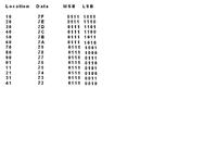
Was wondering if someone might be able to tell me where i have gone wrong with the attached 27C64 Eprom File that has been burned to the Eprom but does not work as intended ?

The Locations are correct, the inputs and the output lines are in the correct sequence but the outputs are reversed in all lines, i.e outputs that should be at level 1 ( 4.9V ) are at 0.01. Likewise, outputs that should be level O ( 0.04 ) are at 4.9V.

Any help would be much appreciated, i have used up all my spare eproms playing with different combos and am no closer to a solution.

Cheers,

Chris S.


Other than adding an octal inverter after the data outputs, I think your only option is to invert all the data bits and program the EPROM again. I presume you have an eraser so you can use them again.
So 0111 1111 (7F) would become 1000 0000 = 80 and so on.

Brian.
 
Thanks Brian,

Do they make an Octal Inverter IC that could handle pulling the inputs in the radio eprom ( 27C64 ) low from 4.9v which closing the Dipswitch on the selected line does ?

I am guessing that if the radio eprom line is at 4.9 and the Channel change line connected to it is at 0.1v then that would be the same as pulling the line low with the Dipswitch.

I have an eraser but something is destroying the chips because after erasing the chips and then verifying they are empty in the burner reprogramming them with a new file creates the message that the chip is not empty.

I am guessing that it may be easier to add the Octal inverter between the two units and leave both eproms alone to operate on their own.

Thanks for your help,

Cheers,

Chris S.
 

There are several octal inverters with "open collector" outputs that would do the job but the cheapest solution is to use a pair of 7406 TTL inverters, they have 6 inverters in each IC so you need to use two and have a few gates left over. Two 7406s are cheaper than one octal chip. You need to "pull up" the outputs with resistors, as the speed here is irrelevant, you can use 10K resistors. Doing it this way means you can safely pull the signals down with the dip switch without risk of an output driving into a short to ground.

The EPROM should be erasable many times, possibly hundreds of times although they do eventually become obstinate to erase and reprogram. What eraser are you using and hw long do you leave them to erase? Typically with an 8W UV tube at about 25mm from the window they take around 20 - 30 minutes.

Brian.
 

Channel Eprom board.JPGThanks Brian,

Looking at a SN7406 chip that has 6 gates that hopefully would do the job.

I only need 5 lines switched from the Eprom for the number of channels in the radio so hopefully this would be enough.

Could you confirm that if i apply 5vdc to VCC and 6 outputs from the Channel change eprom output to the SN7406 chip that the outputs from the SN7406 would be the opposite voltage ( Logic Level ) to the Channel Change eprom outputs ?

I just need the high level to be 4.8V and the low level to be 0.04V or less to switch the inputs on the radio Eprom to select the correct channel. ( Using the Dip switches is only for manually setting the correct channel by pulling the various input lines high or low similar to the Channel Change Eprom. When using the Channel Change unit all the Radio Dip switches are open i.e lines are at 4.8v and the Channel Change unit switches the lines either high or low depending on what channel is selected. ) These connections are marked as "External interface" on the Radio Eprom Circuit Diagram.

The Radio 27C64 has resistors between its input lines and the Dipswitches that when operated on each individual line short that line to Ground ( 0.0V ).
I am hoping that if i can get the outputs from the Channel change Eprom output via the SN7406 to be 0.04v on the correct lines that this will be enough to simulate the dip switch being closed.

If i cannot get the SN7406 chip to work i will buy some more Eproms and try again. The ones i have done successfully all worked first time and did erase ok when needed to but after the first time they would not reprogram with the Burner refusing to install the program.

The Eraser is a Chinese clone ( Unpronouncable ) and it takes approx 45 minutes off its timer to sucessfully blank an eprom that would work again. The Bad Eproms can sit in there for 2 sessions and then still come up bad in the burner.

Thanks for your help,

Cheers,

Chris S.
 
Last edited:

Yes, the high and low states are reversed, if you put a high in you get a low out and vice versa. The actual voltages don't have to be as high as 4.8V or as low as 0.04V, the threshold is somewhere in the 2.4V region so as long as you are significantly above or below that voltage you should be OK. I suggested the 7406 because it has "open collector" outputs, in other words the output isn't driven high from inside the IC, you have to pull each output high with a resistor to +5V outside the IC. My reasoning was that it lets you safely short the output to ground without risk of damage, if the dip switches are not connected directly to an IC output pin, you can use the 7404 IC instead which has outputs which are driven high as well as low from inside the chip.

Sounds like your eraser isn't up to the job. It's a pity we are so far apart because I have tubes of 27C64s here which will probably never be used and you would be welcome to have them. Before buying new ones though, try something: Clean the windows of the EPROMs with a solvent, alcohol or similar should work, then put them in the eraser for about 20 minutes. Then rotate them 180 degrees and give them a further 20 minutes before trying them again. Each cell on the chip surface is extremely tiny and even a minute speck of dirt on the window will cast a large shadow on the cells. Changing their orientation will help to irradiate them from a different angle. There is another trick which I have never tried but I'm assured works on 'tired' EPROMs, ones that refuse to erase or reprogram, you bake them in an oven for about an hour at around 150C. It's not hot enough to melt the package or solder but enough to make the silcon conductive and therefore leak away any charge left in the cells. I would use it as a last resort but it might be worth a go.

Brian.
 

Connections Radio Eprom.JPGThanks Brian,
Will give the revised Eprom program another go tonight with a fresh new eprom straight out of the packet and see how i go.
You may have hit on something with the Windows on the eprom being obscured as some of the ones i have are S/H and have been erased previously before sale.
They programmed OK the first time but trying to erase them resulted in them being U/S.
Looking closely at the window with a Magnifiying Glass it appears that it still has some sort of residue, perhaps Glue from the original label.
Will try some meths on one and see how it goes.
Thanks for the offer of the Chips, with any luck at all it might be sorted out tonight.

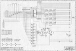
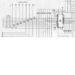
One Question if you could, in relation to the Radio Eprom Circuit attached, can you tell me what Voltage would be required to be applied to each individual external interface line to simulate the Dip Switch attached to that line being closed ( i.e. line being grounded to earth ). This is what the Channel Change Eprom would need to be sending out to work the radio Eprom.

Thanks for your help,

Chris S.
 
Last edited:

Status
Not open for further replies.

Part and Inventory Search

Welcome to EDABoard.com

Sponsor

Back
Top