Continue to Site

Welcome to EDAboard.com

Welcome to our site! EDAboard.com is an international Electronics Discussion Forum focused on EDA software, circuits, schematics, books, theory, papers, asic, pld, 8051, DSP, Network, RF, Analog Design, PCB, Service Manuals... and a whole lot more! To participate you need to register. Registration is free. Click here to register now.

programmable power supply concept

Status
Not open for further replies.

balaji3724

Junior Member level 3
Joined
Jan 25, 2011
Messages
26
Helped
0
Reputation
0
Reaction score
0
Trophy points
1,281
Activity points
1,580
hi
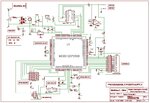
i need help for this project, i searched in net i got one circuit diagram so i am using that circuit diagram please see the circuit diagram so i want to use 8051 microcontroller to do this project so i am clear about hardware but i can't understand the concept of adc process why using adc converstion in this project why i am asking means ,i circuit the digital pot used so i am giving the signal to that ic using the mc.but in circuit from output line take the line and feed to the controller that lines are adc lines.so please explain the concept of this project.
 

Attachments

  • Programmable_Power_Supply_Schematic.jpg
    Programmable_Power_Supply_Schematic.jpg
    232.2 KB · Views: 126
Last edited:

Is it not so that you can set an output voltage, then use the A/D input to confirm the output has been set properly, and if not, do fine adjustment?
 
ok thanks
if i am going to do the adc process then that digital output where i am going to compare please explain the program flow of the total circuit where i am going to give the input ,and how to design the program,please
 

I suppose you would read the keyboard with an input routine, set the digital pot according to the keyboard entry, read the output voltage and display it on the lcd.
There are many ways to write the program.
 
ok sir
you said general concept but i need program flow i am going to write the program using Embedded c. so i need ,for example adc process means how to use the converted digital value where to feed that signal.so sorry i am asking very deep process questions.

---------- Post added at 16:18 ---------- Previous post was at 16:14 ----------

As well as please suggest any digital pot ic already i searched ad7376 but that is not available in dip package so any other ic?

---------- Post added at 16:21 ---------- Previous post was at 16:18 ----------

Thanks sir
 

so please explain the concept of this project
In my opinion, you should ask the authors respectively your project supervisor. Taking a brief look at the schematic, much more questions arise. E.g.
- intended voltage range and setpoint resolution (with the present dimensioning, the resolution seems to be unreasonable low)
- how possible damage of digital pot and current sense amplifier by overvoltage (output > 5V) is avoided?
- specified measurement resolution

ad7376 but that is not available in dip package
You can use adapter boards to solder SO package to DIL socket.
 

your question is right but digital pot accept up to 30v (mention in datasheet)and also op-amp upto18v see the datasheet.
 

but digital pot accept up to 30v (mention in datasheet)and also op-amp upto18v see the datasheet.
More exactly, they accept a respective supply voltage, but not a high input above the (5V) supply. Most likely, an input voltage above rails with pull up the 5V supply, possibly damaging other parts. I think, it's not my job to predict all possible effects, but the circuit seems to be far from fail safe behaviour guaranteed by design. Referring to the previously mentioned problem of digi pot resolution, a 1k potentiometer seems more apprpriate. But AD7376 isn't available with 1K, so I wonder what has been the original specification.
 

Status
Not open for further replies.

Part and Inventory Search

Welcome to EDABoard.com

Sponsor

Back
Top