Welcome to our site! EDAboard.com is an international Electronics Discussion Forum focused on EDA software, circuits, schematics, books, theory, papers, asic, pld, 8051, DSP, Network, RF, Analog Design, PCB, Service Manuals... and a whole lot more! To participate you need to register. Registration is free. Click here to register now.
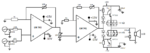
I am trying to found what is wrong with the following circuit. Problem is when I try to simulate it the transistors get burned because they are disippating about 1,21W.
Could anybody explain to me how to give it power so that the speaker works¿?
I'm not an audio guru but I can tell that you need a means of setting the quiescent current in each power transistor. You can change the two series diodes in the bias network to a "boosted diode" configuration. You then adjust the boosted diode to set the standing current in each leg so it operates in class AB. This avoids crossover distortion.
Also, there is no protection against thermal runaway. You need to thermally couple the boosted diode to the power device.
You also have no high frequency roll off on the op-amps.
The power darlington transistors need heatsinks. If the output voltage swing is as high as 8V RMS then the output power is 8W into 8 ohms and each darlington heats with almost 2W.
The 741 opamp was designed 48 years ago! It is noisy and its slew rate cuts its high level frequencies above only 9kHz. A modern low noise audio opamp works perfectly to at least 100kHz.
The circuit is throwing away a lot of output power in its high value emitter resistors and it probably produces high distortion because the darlington transistors are not included inside the negative feedback loop.
This site uses cookies to help personalise content, tailor your experience and to keep you logged in if you register.
By continuing to use this site, you are consenting to our use of cookies.