Continue to Site

Welcome to EDAboard.com

Welcome to our site! EDAboard.com is an international Electronics Discussion Forum focused on EDA software, circuits, schematics, books, theory, papers, asic, pld, 8051, DSP, Network, RF, Analog Design, PCB, Service Manuals... and a whole lot more! To participate you need to register. Registration is free. Click here to register now.

[SOLVED] Problems when trying to prototype RF circuits

Status
Not open for further replies.

Electrojosh86

Member level 3
Joined
Jun 20, 2013
Messages
67
Helped
0
Reputation
0
Reaction score
0
Trophy points
6
Activity points
570
image.jpg
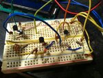
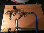
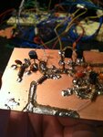
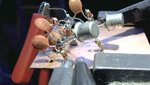
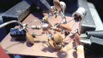
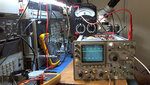
Hello, I am trying to build an RF FM Transmitter that transmits from 88 Mhz- 108 Mhz but I am having a very difficult time doing so. The transmitter I have tested works on a breadboard, which I read is not suppose to due to high capacitance, but for some reason and luck it does work. The problem is when I try and prototype it on a perfboard or anything else the damn thing will not work! The digital tuner part does but the oscillator does not. I have tried the "Manhattan" and "dead bug" construction styles on a PCB with the use of a ground plane and so far it will not work. It will oscillate, as I can sometimes hear on a receiver, but when I hook the PLL up it does not tune or do anything. I am at a loss as to what to do. Is there something I am missing, maybe shorter leads, longer leads, voodoo rituals and animal sacrifices? Or perhaps the oscillator needs to be designed better. I could use some help please. Attached is the schematic. For VT1 I am not using a BF199 I am using SS9018HBU RF transistor and I am aware that the 220k and 470k resistors in the oscillators should be in the ohms and not the kohm range, also thinking that the BFR91 transistor is backwards, corrected on breadboarded circuit and seems to work and for the varicaps I am using MV2109's as that is all I have. If anyone can help that would be awesome.
 

!!There is a mistake on the schematic.BFR91 is not PNP, it's a NPN transistor.
To get good results from this circuit, it should absolutely be implemented on a double layer,thru plated, FR4 PCB.GND connections are very important in such circuits,also connections,couplings,decouplings are very important.Those circuits -normally-don't work on breadboard or something.
 
Thank you for the reply. I did not realize that BFR91 was not to be a PNP but an NPN. Seeing as how the circuit is drawn it does make sense though. I am building, again for the millionth time, on a doublesided copper clad PCB but not sure it is FR4, it is radioshack so.... most likely not. I am cutting tracks and soldering the components down but what is preferred? Deadbug? Manhattan?... I know it is not suppose to work on a breadboard but I guess I had some luck and it just so happened to do so.
 

R17 seems also wrong,it shouldn't be 220K.BFR91 won't work..
 

There are a few problems with this circuit.

1) As said the R11 is too low. You want the voltage on the emitter to be about 0.25 to 0.3 of the supply voltage for good DC stability. R11 should be 22k and up.
2) R12 could be a bit smaller 220Ω to 330Ω is a good range.
3) With the 22pF coupling capacitor you will be loading the tank circuit too much, and the oscillator will most probably struggle to start. It could be connected to the emitter of VT1 but will have ugly harmonics.

The last proposal gives much better results and stability.
 

Attachments

  • non_start.gif
    non_start.gif
    92.2 KB · Views: 157
  • harmonics.gif
    harmonics.gif
    93.4 KB · Views: 173
  • harmonics_low.gif
    harmonics_low.gif
    95.5 KB · Views: 176

I have not look into details, For one, R12 and R17 is so high you hardly have any tail current. I don't believe it's for low current as using 7809 and 7805 regulator wasting a lot of power to start already.

The more important thing, when comes to RF, layout is everything on top of just a ground plane. A ground plane is only a starting point. Take a picture ( close up) and let people look at it. The fact it work with proto board doesn't mean anything, I have seen layout can be so wrong and somehow it work.....barely, you touch it, it stop working!!!
 

Thank you guys for the responses. Should I get rid of the 22pf or just lower its value? Cause there already is a 33pf from the emitter to gnd. I've been trying to build it on a copper 2 sided pcb with no good results. Not sure if FR4 though, it is a RadioShack board and as far as I know, there stuff is not FR4. I've been using and etcher with my dremel tool to cut away the copper and make little islands and tracks for the components but that might not be good. Maybe glueing the components down with leads in the air and soldering them that way? Don't care what it loos like as long as I can get it to work. I'll make something and take a picture, tear it apart for me, criticize it.. I can take it. it
 

First picture is of the working breadboarded model and the second is just the oscillator built around VT1 or Q1. I just want feedback on the PCB layout and technique before I go ahead and built the rest.
 

Attachments

  • photo 1.JPG
    photo 1.JPG
    153.9 KB · Views: 135
  • photo 2.JPG
    photo 2.JPG
    113.2 KB · Views: 125

Build the last circuit I posted, and you should be good. The 22pF should be much smaller, and since you already had it in your circuit, I added the 4.7k resistor. This helps by removing the load placed on the tank circuit by the base-emitter of the next transistor. This will also raise the loaded Q of the tank and give a lower phase noise output from the oscillator. The 33Ω in the emitter help with DC bias stability and raising the input impedance as seen from the base, by the beta factor of the transistor.

The construction at 100MHz is not that critical. The reason it worked by accident on the breadboard is all the stray capacitance's somehow provided the correct feedback for oscillations to start.
 
I am going to keep on going and build the rest on the PCB. What program is that you are using? And where do I get such thing? Also, I take that I should build the varicap section the same way, before the 4.7k?
 

You are correct, keep the varicaps at the same position as before. You should test the oscillator + buffer stage for operation before building the rest of the circuit. If you don't have a scope or freq-counter you can use a radio to get an idea if it is oscillating. For your test you can steer the varicaps with an external DC input via a pot or something.

The program is Multisim https://www.ni.com/multisim/try/ . They may have a student version or you can use a total free package LTspice
https://www.linear.com/designtools/software/?gclid=CIG__7Kq-LcCFQSCQgodrSwA-w#LTspice
 
Last edited:

Okay, rebuilt as per your circuit and no dice. Still does not oscillate and when connected to the PLL. On pin 6 of the SAA1057 there is no change in the voltage at all. Breadboarded model showed voltage fluctuations when messing with the inductor or any other part of the oscillator. It must have something to do with my construction. All grounded points should go to the copper ground plane right? Just making sure. Also, maybe make all components tight with really short leads. Or would you recommend gluing down the components and soldering them in the air above the ground plane. Kinda like a deadbug style. I am at a lose as to what could be the problem. I have attached a photo of what I made that did not work, seeing as it is sloppy it must have something to do with how i am going about building it. Also, I can get rid of that 22pf for a lower if that would be better. Also, which 22pf are you talking about? The coupling cap between the oscillator and the buffer stages?
 

Attachments

  • photo 1(1).JPG
    photo 1(1).JPG
    1.8 MB · Views: 128

Before you do anything, clean the board. Your circuit is high impedance, all the flux is going to affect the circuit. You'll create parasitic paths. Use iso propanol ( rubbing alcohol) and tooth brush and clean it. Then blow with those compressed air ( common in computer store).

- - - Updated - - -

Before you do anything, clean the board. Your circuit is high impedance, all the flux is going to affect the circuit. You'll create parasitic paths. Use iso propanol ( rubbing alcohol) and tooth brush and clean it. Then blow with those compressed air ( common in computer store).

Also, ohm the circuit out after cleaning to make sure you did not short out anything as solder can easily bridge over.
 

The 22pF is the one to the buffer stage. What test equipment do you have to measure with?

- - - Updated - - -

Check your connections carefully. I tested the circuit on pcb now, and it works as suggested by the simulation results. I used common 2N2222 transistors, so they have much lower gain at 100MHz, thus the measured output is lower. I used a 10pF for coupling. Something like a BFR91 will have a lot more gain at 100MHz, so the 10pF will be too big in that case and may need a series resistor as well. The best way is to look with a scope to see that the output is not clipped.

The frequency is high and will drop when the varicap section is added.
 

Attachments

  • test_osc.gif
    test_osc.gif
    43.6 KB · Views: 139
  • test_osc_out.jpg
    test_osc_out.jpg
    247.8 KB · Views: 129
  • test_osc_out1.jpg
    test_osc_out1.jpg
    292.4 KB · Views: 147
Last edited:

Still does not oscillate and when connected to the PLL. On pin 6 of the SAA1057 there is no change in the voltage at all.
Involves two points:
1. The circuit should oscillate. How do you check for?
2. If the circuit does oscillate, it might still not feed sufficient power to the PLL FFM input. Where did you get the idea about a 10 k series resistor? FFM input impedance is said to be 135 ohm, minimum input voltage is 10 mV. So it can only work if you have > 750 mV RF level at the buffer output
 

I do not have an scope or a freq counter, all I have is a meter and a receiver. I am not using 2n2222 transistor, I don't have any but I am trying to use SS9018HBU RF transistor and getting no results. I have 2n5088 and 2n3504 transistors too. I do have scopes at work, maybe I should take it there and scope it, but don't think that they would let me.

I got the idea to use a 10k series resistor to the PLL FFM from the diagram, I did not design the circuit but merely trying to build it. As pointed out, there are flaws and if that's one of them I would be happy to change it.
 

You could check your DC conditions for signs of oscillation with a meter sometimes. Old rule #3: Whenever you get DC measurements that do not make sense, suspect something is oscillating!https://www.edaboard.com/threads/19701/
This can be demonstrated with this design. When oscillator is working you will get strange reading on the base and emitter.

Below I have indicated the readings from my circuit. I removed the 33pF cap to stop any oscillations, and these voltages are in blue. Then with the oscillator running, the measurements at the base and the emitter is almost identical. You don't measure the normal 0.5V to 0.7V drop as expected.

Can you provide these reading from your circuit?
 

Attachments

  • osc_voltages.gif
    osc_voltages.gif
    12.7 KB · Views: 133
Last edited:
I will rebuild and post my results. Just eBayed some oscilloscopes to see what the prices were. Not bad, not as much as I expected. What bandwidth should I go for? I feel that this would be so much easier with one.
 

There are a lot of old Tektronix 465 and 475 scopes around. Get the highest bandwidth you can afford + probes. The 465 is a 100MHz scope, and the 475 can do 200MHz. They are quite easy to repair, and service manuals can be downloaded free. Stay away from the Tek 485 which is a 350MHz unit. Not easy to work on if you don't know what you are doing.

Important: Make sure the tube is working when getting one of these old scopes!

Picture is of a Tek 485 I recently repaired that had quite a few problems.
 

Attachments

  • 485.jpg
    485.jpg
    215 KB · Views: 144
Last edited:

Status
Not open for further replies.

Part and Inventory Search

Welcome to EDABoard.com

Sponsor

Back
Top