cadenceUK
Member level 5
https://obrazki.elektroda.pl/10_1187239679.jpg
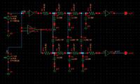
I am using RC model to test delay in this circuit.
However the RC model attenuates the signal rather delaying it from volts to milivolts.. clik 2 c d simulation... its nt clear bt u cn c tht output is in mv and i/p is in V.
https://obrazki.elektroda.pl/92_1187239941.gif
What can be the problem in this?
regard the components except R & C as simple buffer/repeater/driver or inverter!
Thank you!
Added after 5 minutes:
https://obrazki.elektroda.pl/92_1187239941.gif