Continue to Site

Welcome to EDAboard.com

Welcome to our site! EDAboard.com is an international Electronics Discussion Forum focused on EDA software, circuits, schematics, books, theory, papers, asic, pld, 8051, DSP, Network, RF, Analog Design, PCB, Service Manuals... and a whole lot more! To participate you need to register. Registration is free. Click here to register now.

problem with notch filter implementation

Status
Not open for further replies.

zula

Full Member level 2
Joined
Jul 5, 2009
Messages
147
Helped
21
Reputation
40
Reaction score
17
Trophy points
1,298
Location
Turkey
Activity points
2,043
Hi all,

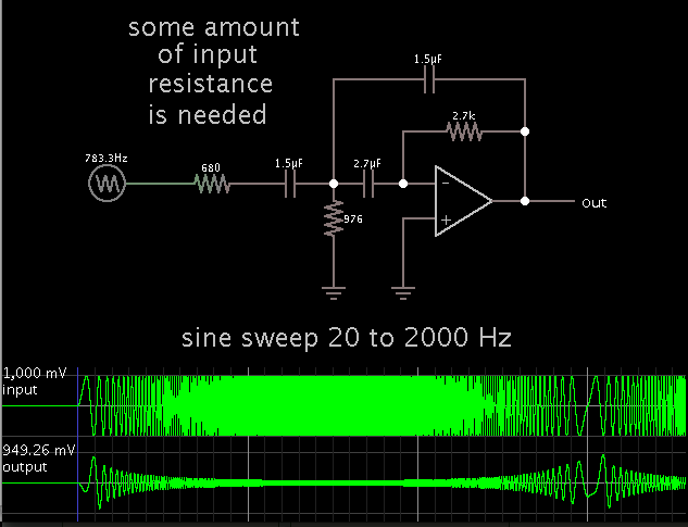
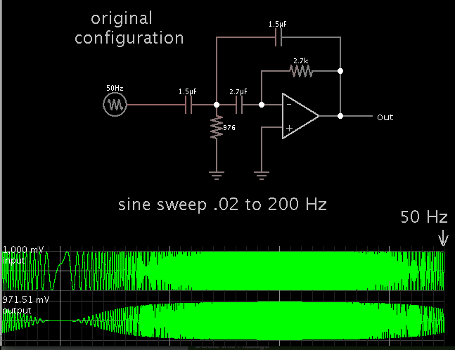
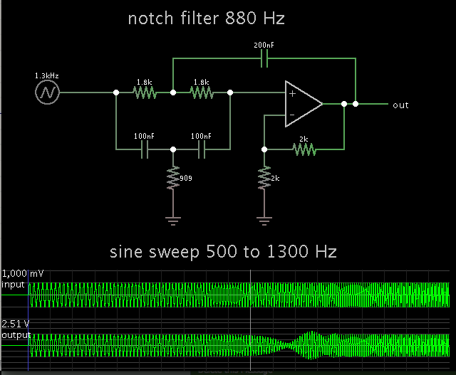
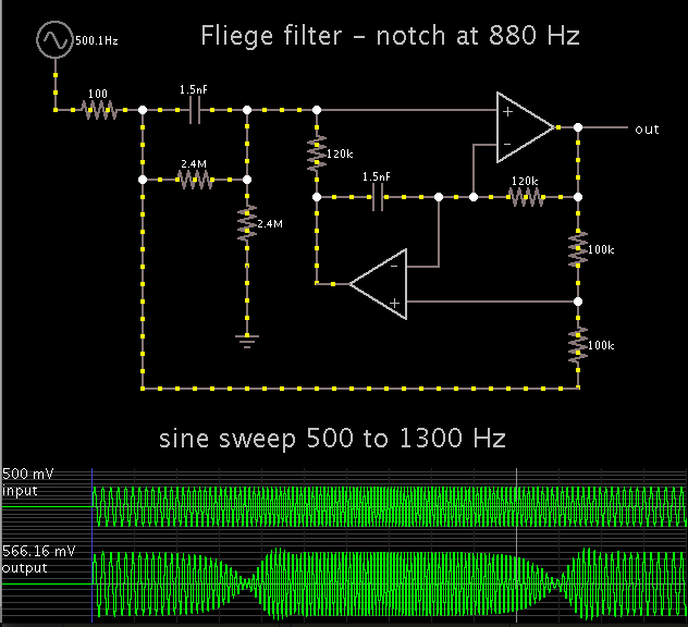
Iam trying to implement notch filter. I used FilterLab software to design it. Circuit is below.
Iam working on an Acustic Device that produce 880Hz tone. On the other hand i have a microphone circuit to detect ambient voice level.
So i have to eliminate 880Hz at the microphone outputs.

But this circuit doesnt works. Iam observing it with osciloscope there is still 880Hz and its harmonics.

Please give me some advices iam stuck.

mic module.jpg
 

I guess you didn't check the exact transfer function of your design or the effect of 1% component variations? It's quite instructive, I think.

I strongy suggest to refer to a bandstop filter topology that can be tuned for exact center frequency and isn't that sensitive to component variations.
 

Your first filter needs some amount of input resistance, in order to work. It also needs a bipolar supply.


Looks like it's a low pass filter. It will filter out practically all of your incoming audio.
 

Your first filter needs some amount of input resistance, in order to work.
I suggest to rephrase: As shown, the filter circuit can't be implemented with usual OPs. Adding a source resistance ruinates the filter characteristic however.

Looks like it's a low pass filter. It will filter out practically all of your incoming audio.
It's actually a high pass filter, as claimed. But not a reasonable design.

Both filters are examples of using a filter design tool without understanding the limitations of real world electronic circuits, I think.
 

I suggest to rephrase: As shown, the filter circuit can't be implemented with usual OPs. Adding a source resistance ruinates the filter characteristic however.
...
It's actually a high pass filter, as claimed. But not a reasonable design.

To follow up on this...
I reverted to the original schematic (with no input resistance). I see that by applying a much slower frequency sweep, it does indeed become a high-pass filter.


The 70.7% amplitude is around 50 Hz.
 

Yes. The problem is of course, that the OP is capacitively shorted against the source. A real OP will become unstable in this situation.
 
  • Like
Reactions: zula

    zula

    Points: 2
    Helpful Answer Positive Rating
Yes. The problem is of course, that the OP is capacitively shorted against the source. A real OP will become unstable in this situation.

Some capacitors would be connected but without series resistance. I imagine it can lead to parasitic oscillations.

Evidently the simulation (Falstad's, my post #3) did not reveal this. Instead highs were attenuated. With further testing, now I see it also eliminates lows below 30 Hz or so (as intended). It does so with either a high or low input resistance.

- - - Updated - - -

Since there is always a certain 'hidden' resistance upstream, and yet we don't always know what it is, that makes it easy to forget how it can influence the circuit we are focussing on. So I have tried to get in the habit of putting a resistor at the input, in order to stay close to reality.

-----------------------------------

Zula, in case you're still there...

I made a simulation of the notch filter. It resembles the twin-tee concept.

It works at 880 Hz.

 
  • Like
Reactions: zula

    zula

    Points: 2
    Helpful Answer Positive Rating
I should mention that the high-pass filter is a regular second order MFB design. But it involves some implementation problems with capacitive OP loading, thus I would prefer a Sallen Key topology for the high-pass.

The problem addressed in the original post is however related to the notch filter.
 

thank you for all your responses. Iwill change my high pass filters metodology.
Anyway it is not reaaly important for my design. notch is much more important for me. Actually i didnt test high pass i bypassed it on the pcb.
At this point thank you for your simulation Bread but ive already did this simulation yes it works with simulation but when i try it on the real pcb with my osciloscope it doesnt work.
Now iam trying to find real cutoff frequency of my notch filter.
 

1.

Did you pre-amp the microphone signal? It only puts out a few mV as a rule. It may need to be at greater amplitude, for the notch filter to perform.

2.

In case you want to try another notch filter topology, there is the Fliege filter.


Hi Bread,

It is really hard to realize this filters on the real pcbs. Because iam trying to use %1 tolerances for resistors and capacitors. Even with %1 it is a huge difference.
When i measure 1.5nF with multimeter i see it is 2nF instead of 1.5nF.(But i am not sure my multimeters sensivities) And i run the simulation with this real values then i see the notch frequency is 630Hz now.
But iam measuring the outputs of filter with the 630Hz input signals. Filter didnt suppres this signal again. I dont know where is the problem?

By the way i have a preamp circuit for the microphone. It is working well.
 

Unless your capacitors are exactly specified with 1% tolerance you can hardly expect a similar precision. Unfortunately, even 1% accuracy isn't enough for the notch filter circuit you have posted. That's why I suggested to use a topology that can be tuned with a single resistor and whose notch characteristic isn't sensitive to capacitor tolerances.
 
  • Like
Reactions: zula

    zula

    Points: 2
    Helpful Answer Positive Rating
When i measure 1.5nF with multimeter i see it is 2nF instead of 1.5nF.(But i am not sure my multimeters sensivities)

I once had to match a set of capacitors to make a filter that would extract a single audio frequency. I needed high Q so I chose a bandpass biquad type.

To match the capacitors I took several of the same value, then put them one at a time in a simple oscillator circuit (made from two inverter gates). I observed the frequency and wrote it down on paper, and placed the capacitor next to it.

As soon as I found 3 which yielded the same frequency, I knew I had matching capacitors.

My DMM shows ohm values to 4 digits, so it was easy to match resistors.

You may need to resort to using 3 or 4 potentiometers, and adjust them to get your desired frequency.
 
  • Like
Reactions: zula

    zula

    Points: 2
    Helpful Answer Positive Rating
As you said i can match the values with potentiometer but i have to plan production also. I will produce 1000qty of this boards.
So it is really unacceptable time loss for me. I dont understand how engineers do this type of filters with large quantities.

Anyway thank you very much for your helps.
 

Status
Not open for further replies.

Part and Inventory Search

Welcome to EDABoard.com

Sponsor

Back
Top