Continue to Site

Welcome to EDAboard.com

Welcome to our site! EDAboard.com is an international Electronics Discussion Forum focused on EDA software, circuits, schematics, books, theory, papers, asic, pld, 8051, DSP, Network, RF, Analog Design, PCB, Service Manuals... and a whole lot more! To participate you need to register. Registration is free. Click here to register now.

Problem with IR2153 high side output

Status
Not open for further replies.

saeedmns68

Junior Member level 1
Joined
Mar 5, 2016
Messages
18
Helped
0
Reputation
0
Reaction score
0
Trophy points
1
Activity points
142
Problem with IR2153 high side

Im making a half bridge 300v 14khz square wave power supply by using two ultra fast IGBTs and a IR2153 gate driver,when the power part of the circuit is inacvtive(Vcc=0 V) the gate-emitter waveform on high side IGBT is good with peak to peak voltage of VGE=11200mV , but when the power is activated and no load is at the output of the circuit(IC=0) the waveform will contain high frequency noise with 7000mV mixed with original waveform VPP=11.3V.bmp peak to peak ,the power supply of high and low side VGE is two isolated L7812CV output,what can be wrong in my circuit?pls help me
View attachment VGE HIGH AFTER CONNECTING POWER VPP=18.5.bmp
 

Im making a half bridge 300v 14khz square wave power supply by using two ultra fast IGBTs and a IR2153 gate driver,when the power part of the circuit is inacvtive(Vcc=0 V) the gate-emitter waveform on high side IGBT is good with peak to peak voltage of VGE=11200mV , but when the power is activated and no load is at the output of the circuit(IC=0) the waveform will contain high frequency noise with 7000mV mixed with original waveform VPP=11.3V.bmp peak to peak ,the power supply of high and low side VGE is two isolated L7812CV output,what can be wrong in my circuit?pls help me


IRS2153DSPBF-circuits.jpg


VGE HI BEFORE CONNECTING POWER VPP=11.3V.jpg


VGE HIGH AFTER CONNECTING POWER VPP=18.5.jpg
 

Most likely a measurement artifact. How are you measuring high side gate voltage?
 

I measure by an oscilloscope Im sure oscilloscope is working well.frequency is 14kHZ and each horizental division is 2.5V
 

Hi,

You are measuring high side.
So you need a differential measurement.
One at VS the other at HO.

Are you using two different channels for that and use the scope "difference" function?

* If so, then either your probes are overload ( 300V !) --> use HV probes.
* Or your scope input stage is overload: --> select a higher input voltage range on both channels.

Klaus
 

Klaus I measured with one probe only at HO and VS .The VGE voltage peak to peak is 11V .300V is for the power side (Vcc) .I measured VGE of low side with that probe and os and it had no noises
 

I measured with one probe only at HO and VS
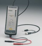
What kind of probe? You need a high voltage differential probe for a reliable measurement, under circumstances a difference measurement with two equal probes as mentioned by KlausST can work.

probe.jpg
 

I have two similar appropriate high voltage probes
 

Hi,

Most probably you use an active probe..
* Is there a limited common mode input voltage range?
* or limited dV/dt?
* Is the battery OK?

If you interchange both probes? what happens?

Klaus
 

There is no active probe, my probe has 2.2Mhz safe response output and no battery I used. I interchanged probes but the result is same

- - - Updated - - -

Today I changed the polarity of my measurement(mesuring Vge and Veg) the noise got down!!!what is the problem??
 

Today I changed the polarity of my measurement(mesuring Vge and Veg) the noise got down!!!what is the problem??
 

welcome to the challenging world of trying to measure high side gate drive waveforms when the emitter is going up and down at switching freq
 

its very tricky to measure if the coax of the scope probe is flicking up and down at sw freq
 

Status
Not open for further replies.

Part and Inventory Search

Welcome to EDABoard.com

Sponsor

Back
Top