coates
Member level 1

Hi guys,
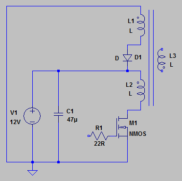
I'm trying to improve my understanding of converters and HF transformers by prototyping a single transistor forward converter using a pulse transformer. However the waveforms are not as I expected.

The MOSFET is a logic type and driven through R1 by PWM. The pulse transformer is the Murata 77208C. According to the datasheet all windings are the same. The diode is UF4005.
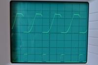
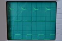
Here are the waveforms I'm getting for MOSFET drain voltage (top) and gate voltage (bottom). Time base is 5us/div. Top trace is 10V/div, bottom trace is 5V/div.


The top photo is for low duty and the bottom is approaching 50% duty.
I expect the drain voltage to spike to some arbitrary voltage as the leakage inductance on the primary winding discharges, then settle to +24V (12V * 2) as the reset winding L1 discharges through D1 and back to +12V. Then when the core is fully discharged the leakage inductance will start ringing about +12V with the drain capacitance.
The top waveform confuses me, in particular. It leads me to believe that the reset winding isn't working at all because the drain voltage doesn't return to +12V. However, I can't see why. Please help!
Many thanks.
I'm trying to improve my understanding of converters and HF transformers by prototyping a single transistor forward converter using a pulse transformer. However the waveforms are not as I expected.

The MOSFET is a logic type and driven through R1 by PWM. The pulse transformer is the Murata 77208C. According to the datasheet all windings are the same. The diode is UF4005.
Here are the waveforms I'm getting for MOSFET drain voltage (top) and gate voltage (bottom). Time base is 5us/div. Top trace is 10V/div, bottom trace is 5V/div.


The top photo is for low duty and the bottom is approaching 50% duty.
I expect the drain voltage to spike to some arbitrary voltage as the leakage inductance on the primary winding discharges, then settle to +24V (12V * 2) as the reset winding L1 discharges through D1 and back to +12V. Then when the core is fully discharged the leakage inductance will start ringing about +12V with the drain capacitance.
The top waveform confuses me, in particular. It leads me to believe that the reset winding isn't working at all because the drain voltage doesn't return to +12V. However, I can't see why. Please help!
Many thanks.

