Continue to Site

Welcome to EDAboard.com

Welcome to our site! EDAboard.com is an international Electronics Discussion Forum focused on EDA software, circuits, schematics, books, theory, papers, asic, pld, 8051, DSP, Network, RF, Analog Design, PCB, Service Manuals... and a whole lot more! To participate you need to register. Registration is free. Click here to register now.

Problem with Flyback DCM converter

Status
Not open for further replies.

Jc_eletrica

Newbie
Joined
Feb 11, 2022
Messages
5
Helped
0
Reputation
0
Reaction score
0
Trophy points
1
Activity points
54
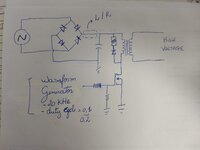
Hi! I've been working with Flybacks for a short time, I managed to design some at input voltages of up to 30 V, so far. But now, it's the first time I build one with a voltage of 220VAC and I'm facing a problem, I hope someone can give me a 'light'. I initially set up the following schematic, based on more than one source of Flyback calculation in discontinuous mode and the values were similar between them. Go to the assembly.
The problem:
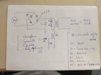
Even measuring the primary inductance with an LCR meter, and sizing the components according to the Flyback manuals, the MOSFET and the rectifying diodes burn out in a few milliseconds connected through a circuit breaker.
I tried to carry out tests by changing the capacitor's load current limiter, imagining that was it, but the resistor consumes a lot of power and with the maximum inductance I had, (2mH), the problem was not solved. Turning the circuit on for 10ms and current limiting with inductor, I was able to see the secondary work. When increasing the time the MOSFET explodes.
I am not able to identify the cause of these current spikes.
Any help is welcome!
 

Attachments

  • IMG_20220211_170239999.jpg
    IMG_20220211_170239999.jpg
    567.5 KB · Views: 98

Hi,

My guess: Inductor saturation.

The schematic is a standard flyback. But without part values it's almost useless.
For better assistance we also need PCB layout.

Klaus
 

Whats you intended Vout and Pout....or is this just "general investigating" kind of thing?
Do you use ultra fast diodes?
You have no output capacitor or diode, why is this?
You also need to show the phasing of the transformer
You shoudl wear goggles when doing mains stuff with open PCBs.

If you want a guide on how to do a low power offline flyback, then power integrations offers a full online design service, giving full bom and part nos, and transformer instructions etc etc
 

found this - looks good:

--- Updated ---

p.s. a flyback should always have a min load and a volt meter on the o/p for the primitive testing you appear to be doing ....
 

Hi,

My guess: Inductor saturation.

The schematic is a standard flyback. But without part values it's almost useless.
For better assistance we also need PCB layout.

Klaus
Thanks for the idea, Klaus. I don't have a PCB layout yet because it's a bench test, on a breadboard yet. I'm attaching a new file with the different values I'm using, where for items M1 and B1 tested with two models. I hope this clarifies the situation a little more. For now I don't need precision in the output data, my objective initially is just to generate an electric arc, in the ends of two metallic rods that come out of the secondary of the transformer.

Calculation data:
I _pri_peak = 4A
I_sec_peak = 15mA
I_pri_RMS = 1A
i_sec_RMS = 8mA
Lp = 670uH
 

Attachments

  • IMG_20220214_085029427.jpg
    IMG_20220214_085029427.jpg
    495.8 KB · Views: 81

Whats you intended Vout and Pout....or is this just "general investigating" kind of thing?
Do you use ultra fast diodes?
You have no output capacitor or diode, why is this?
You also need to show the phasing of the transformer
You shoudl wear goggles when doing mains stuff with open PCBs.

If you want a guide on how to do a low power offline flyback, then power integrations offers a full online design service, giving full bom and part nos, and transformer instructions etc etc
Hi! Thank you so much for your feedback! I'm wearing goggles yes and timing the VCA input, to reduce security risks. My biggest goal at the moment in relation to the output is to generate an electric arc at the end of two metallic poles of the secondary. My output data is still stipulated, based on the last Flyback I did with a 12Vdc input, where the current calculation was Io = 1mA and Vout = 18kV. As this had worked, as I needed more intensity in the arc generation, I increased the current for this new test.

Current calculated output data:
Vout = 18kV
iout = 5mA

But really the concern at the moment is not to verify if this output is correct, because I don't have equipment for such verification yet. I need to initially generate the electric arc.
--- Updated ---

found this - looks good:

--- Updated ---

p.s. a flyback should always have a min load and a volt meter on the o/p for the primitive testing you appear to be doing ....

Hi! Thank you for the answer! My output is 18kV to try to provide a high voltage meter to control these levels. Regarding the charge, my idea now is just to break the dielectric and generate an arc. In the future then this output will be applied a capacitive load.
 
Last edited:

Do you mind to tell a few transformer parameters, n1, n2, core cross section, magnetic path length, air gap? Did you measure secondary winding self resonance frequency, are you sure it can operate at 20 kHz.

What happens if the arc load breaks during primary on time, shouldn't you better operate the converter in current mode?
 

18kV sec's can be tricky to wind - need to be in separate sections up to about 2kV each, to reduce capacitance and increase voltage withstand
 

Do you mind to tell a few transformer parameters, n1, n2, core cross section, magnetic path length, air gap? Did you measure secondary winding self resonance frequency, are you sure it can operate at 20 kHz.

What happens if the arc load breaks during primary on time, shouldn't you better operate the converter in current mode?
Hi! Thank you for your answer! As Klaus suggested, I believe that saturation was the main problem, because my colleague who assembles/designs the transformers did not check the saturation parameter this time. Evaluating now, the calculation really indicates saturation. After adjusting this, I will also check the resonance issue, which makes a lot of sense, because on the LCR meter it was possible to see the abrupt differences in inductance according to the imposed frequency. At the moment I don't have components to work with current control, but I will really try to do that soon. Follow the transformer data, I will try to correct the saturation problem immediately.

Transformer:

N1 - 32
N2 - 5400
CROSS SECTION - 98,52 mm2
MAGNETIC PATH LENGTH - 154,11 mm
Without GAP

Thanks!
 

18kV sec's can be tricky to wind - need to be in separate sections up to about 2kV each, to reduce capacitance and increase voltage withstand
Hi! Thanks for your contribution! The spool that is being used in the transformer is divided into sections, at first to avoid this problem, as you pointed out.
 

Status
Not open for further replies.

Similar threads

Part and Inventory Search

Welcome to EDABoard.com

Sponsor

Back
Top