Continue to Site

Welcome to EDAboard.com

Welcome to our site! EDAboard.com is an international Electronics Discussion Forum focused on EDA software, circuits, schematics, books, theory, papers, asic, pld, 8051, DSP, Network, RF, Analog Design, PCB, Service Manuals... and a whole lot more! To participate you need to register. Registration is free. Click here to register now.

problem with an AM transmitter

Status
Not open for further replies.

andreidaniel

Member level 2
Member level 2
Joined
Sep 18, 2010
Messages
42
Helped
1
Reputation
5
Reaction score
2
Trophy points
1,288
Location
Romania, Iasi City
Visit site
Activity points
1,818
Hi! I bought a two valve AM transmitter (MW or SW, depends on coils used).
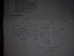
4efea5d195fac30c8e51a3d7ec75924b.jpg

The coils are switchable and in the diagram is shown the version when them are connected.

I made the kit for MW and it worked. After a while, when I was already tired unfortunately,by mistake I tried to bring closer the two inductances of 180uH with a patent.. At that time the kit was powered by 1,5V cell D + 44V (it works from 27 to 90V depends on what power do you need, and the recommanded voltage is 36V) from 5 cells 9V .. I made practically a short circuit between A and F points where are the two coils... Please have a look on the diagram again and tell me if it could be possible to be damaged the RF tube.. I measured the inductances because it got out fume and now one has 27uH and the other 16uH (from 170uH)..

Please I am desperate.. I tried even to make a SW coils with 12 wires but I cannot receive anything from 1,7 to 18MHz... Also I saw that on the top of RF tube is something like a rainbow..purple...is it normally? I did not remember if that was when I opened the box.
**broken link removed**
 

That looks like a very old design - I haven't seen a DF96 or 1R5 in maybe 40 years!

Shorting A to F would connect L1 and L2 in series across the 44V supply so it may have burned them out but unless C5 is rated at less than 44V it should not damage anything else.

The top of the glass should be silver although it isn't unusual to see some pattern in it. It comes from a small magnesium flare which is ignited to burn away any remaining air after manufacture and it usually turns white if air has managed to leak in through a fracture in the glass. I doubt any electrical factors would make it change color.

Brian.
 

It looks like you learnt a valuable lesson to use plastic screwdriver for tuning gaps on magnet wire, as it appears the grounded L2 shorted out with the grid connected L1 possibly causing thermionic emission of grid particles in the inert gas, now making the gas "leaky" and hotter which in turn causes the grid to glow with possible HF corona and UV/purple/blue emissions from partial discharge.

My old Bogan audio tube power amp used to turn blue on top before the tubes failed and would occasional spit out audible frequent static discharges (stronger than "partial discharge) but weaker than corona. Try winding your own coils with magnet wire on a plastic tube hollow tube and insert tiny ferrite slug to adjust coupling and inductance of L1/L2 ratios and LC resonance. Mutual coupling of coils widens bandwidth a bit but with steep skirts of high Q.


Or consider another design kit.
 
Last edited:

Fortunately the valve wasn't borken. I decided until will come the new RF tube and those inductances to test the kit with a ferrite antena..with less performances. It worked. The inductances from the clip are 4, series 2 + 2. I thought that will sum their values 100uH + 100uH to have a final one of 200uH but I was wrong. I put each other on the LCR meter and from 100uH only 71 to 73uH had each...and when I sum two about 109uH had.. I reload the test and worked pretty good.


The signal is trong if I look to the LED indicator/magic eye or uA. But! But if I turn up the volume more from the iPod will appaer distorsion... The modulator is not powerfull and in this case can be saturated with a strong signal OR it is preffered a lower level to not loose the frequency oscilator? How can be solved this problem and how can I obtain a higher power (and also a higher range..now covers two rooms..mine and the near bedroom + a little bit from living)

a) A high power tube with cathode ( not with filaments like this that provide electrons)
b) with and RF amplifier with 1 or two stages
c) both A + B ?
 

TX is just a short name for Transmitter. The equivalent is RX for Receiver.

I would expect a range of > 100m with a rooftop antenna, even one which is not tuned to the right frequency but it is possible the building construction is shielding the signal. What Chuckey is telling you is there is an optimum length for the antenna, ideally 0.25 wavelengths long. You can read the wavelength off your receiver if it has a scale in Metres, otherwise it is C/frequency where C is the wave velocity, typically 300Mm/s. For example a 1MHz signal has a wavelength of 300m so a quarter wave antenna would be 300/4 = 75 metres long.

As it is unlikely you can install a 75m antenna, the next best thing is to 'tune' your existing antenna electrically. It isn't as good as the correct length of wire but it will be better than you have at the moment. Try adding another coil and a variable capacitor in series with the antenna. It is difficult to predict the values you will need but I suggest you start by using about the same length of wire that you need to extend the existing antenna and wind it into a coil. So approximately 65m of wire, you can remove turns if necessary or you could try making a connection to the coil after every 20 turns or so so you can swap the connections easily without unwinding it. Use the biggest value variable capacitor you can find. It is VERY important that you shield the coil from the ones you already have as they may interact with each other and make the circuit oscillate at the wrong frequency. Without measuring equipment it is difficult to describe how to tune if for best output power but you should hear a peak in the signal as the coils/capacitor are adjusted properly.

Brian.
 

" ideally 0.25 wavelengths long" What does it mean? For example at 1000KHz (300m) the lenght of the antena should be 0,25 x 300 = > 75m high ?

"Try adding another coil and a variable capacitor in series with the antenna" What does it mean? After 10m of cable should i insert a LC tuned circuit and after it another 10m of cable? Should be something passive?

I like this kit. Legally...do the guys research you if you transmit at the end of the MW for example at 1600KHz? Or after 300Khz to 400Khz ( the old LW extended domain?) in a range of 400-500m ? Nowadays receivers don't have LW..only a few and frequencies after 260 or 280KHz they don't receive. What about 1,7 to 5,9mhz? Nowadays receivers don't receive SW..only a few receive from 5,9MHz to 18 or 21MHz. Rare digital receivers can tune from 1,6 to 26 or 30MHz. My valve receiver Graetz can tune from 1,7-5,9 and 6-18MHz.
 

The person from where I bought the kit told me this:
"Using a short antenna of a few meters requires MATCHING

The easiest way to do this is a tapped loading coil (150 turns copper wire on 50mm pipe, tapped every 10 turns)

Search Google for "BASE LOADED MW ANTENNA""

My question is how to make and how to connect the coil?
 

The length we are referring to is the length of the antenna, the height above ground is not as important but keeping it as elevated as possible will help.

The 'matching' is what the coils and capacitor I suggested is for. The subject is complicated but to put it as simply as possible, the transmitter will radiate most signal when antenna is a a certain length, adding the matching network makes the transmitter think the antenna is correct when it actually isn't. Imagine this: you have a rope tied to a wall at one end and you raise and lower the other end with your hand. The speed you move your hand is like the frequency of the transmitter and the length of the rope is like the length of the antenna. You will see that at slow speed the rope just hangs and and high speed it waves irregularly. If you get the speed just right it makes a steady 'standing' wave where you have one or more peaks that stay the same distance along the rope, this is called resonance. Different lengths of rope will resonate at different speeds. The same thing happens with the radio waves and the antenna length, if you get 'resonance' the electrical signal from the transmitter produces fixed voltage and current peaks along the antenna length and it radiates most signal.

The matching network 'fakes' the additional length and makes the antenna wire resonate, it isn't as good as using the ideal length of antenna because the matching network (coil and variable capacitor) do not radiate any signal themselves. There are several types of matching network but a coil and capacitor in series connected between the transmitter output and the antenna should be good enough for your needs.

Almost certainly the transmitter will not be legal unless you have a broadcast license from your government so you take a risk by using it but I'm not sure if anybody would actually try to track you down. Bear in mind also that if you broadcast music or other recordings you may be breaking copyright law as well. I worked in Timisoara for a while but never investigated broadcasting there (I do have a license) so I'm not sure who you would contact for advice.

Brian.
 

Status
Not open for further replies.

Part and Inventory Search

Welcome to EDABoard.com

Sponsor

Back
Top