myblues
Newbie level 5
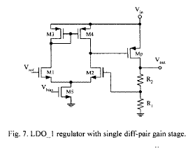
Hi, I'm studying ldo design. I've met a problem of ac simulation. In figure below, one of input of error amp is connected to the feedback net.
When I do .ac simulation, I put a spiral between input of EA and feedback net. So the DC voltage of input achived and ac signal is blocked. But how can I add ac signal? Ples. see below:
v1 in 0 ac 1
Is this ac sentence right? It has no dc voltage! Other words the dc voltage is zero.
If I give a dc voltage like this:
v1 in 0 dc 1.2 ac 1
then the dc voltage from freedback net is not taken effect.
To solve this problem I put a capacitor between the ac signal and the input. But in this way I cannot see the ac characteristic in low frequency.
So I have no idea about it.
Thanks!
(By the way, are there any problem in my picture?)
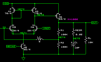