Continue to Site

Welcome to EDAboard.com

Welcome to our site! EDAboard.com is an international Electronics Discussion Forum focused on EDA software, circuits, schematics, books, theory, papers, asic, pld, 8051, DSP, Network, RF, Analog Design, PCB, Service Manuals... and a whole lot more! To participate you need to register. Registration is free. Click here to register now.

[SOLVED] Problem whith RFM12BP module.

Status
Not open for further replies.

hamed8419215

Member level 5
Joined
Mar 3, 2010
Messages
86
Helped
26
Reputation
52
Reaction score
26
Trophy points
1,298
Location
mashhad
Activity points
1,795
Hi ti all.
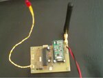
I have designed a circuit with RFM12BP that sends and receives data.
My circuit does not work properly. The circuit does not work, but when i touch a component of circuit it works!
Please help me. thanks.
 

it can be either stray capacitance effect or improper grounding of your system.... check the grounding and ensure proper grounding is there put small value capacitors at the output or the place where you touch....
 
I have used a single layer PCB and it has not any ground plane.
when the circuit is left alone, the power transistor of RFM12BP takes to hot and micro controller does not preform code. and when i touch the circuit or place it on an metal surface, it works.
 

what is the power supply Voltage and current rating... check the regulator in the module, the output voltage it measures when getting heated...

---------- Post added at 11:31 ---------- Previous post was at 11:30 ----------

https://www.ottomat.hu/archivum/RF_modulok/RFM12BP.pdf
 
I have used a 12V-1A switching power supply. the output of power supply when getting heated is about 11.5V. but the output of LF33CV is varying between 2.9 to 3.4.
 

I have 2 of this module. i r=test both of them and i get same result.
 

this is a photo of my circuit (sorry for low resolution). I touch both of LED wires and antenna and the circuit works.
 

Attachments

  • 1.JPG
    1.JPG
    59.1 KB · Views: 105

I know that the program of MCU has not any problem (because some time the circuit works) and i think that hardware should have problem.
 

hi, i have problem to make comunication betwin 2 rfm12bp modules, i wana make remote controller with them bt all samples and data i found on internet not help me:(. I am not so good in programing micors bt i programed in avr bascom. Rfm12bp have transmitt and recieve pins, i try to connect this pins to 3.3 v and still nothing happens, canot get any data from transmitter to reciever. Any help are velcome!

p.s. Sorry for my bad english!


here is my code in bascom-avr
transmitter:

Code Basic4GL - [expand]
1
2
3
4
5
6
7
8
9
10
11
12
13
14
15
16
17
18
19
20
21
22
23
24
25
26
27
28
29
30
31
32
33
34
35
36
37
38
39
40
41
42
43
44
45
46
47
48
49
50
51
52
53
54
55
56
57
58
59
60
61
62
63
64
65
66
67
68
69
70
71
72
73
74
75
76
77
78
79
80
81
82
83
84
85
86
87
88
89
90
91
92
93
94
95
96
97
98
99
100
101
102
103
104
105
106
107
108
109
110
111
112
113
114
115
116
117
118
119
120
121
122
123
124
125
126
127
128
129
130
131
132
133
134
135
136
137
138
139
140
141
142
143
144
145
146
147
148
149
150
151
152
153
154
155
156
157
158
159
160
161
162
163
164
165
166
167
168
169
170
171
172
173
174
175
176
177
178
179
180
$regfile = "m88def.dat"
$hwstack = 40
$swstack = 40
$framesize = 40
 
$crystal = 8000000
$baud = 4800
 
'*******************************************************************************
Declare Sub Freq_rfm12
Declare Sub Init_rfm12bp
Declare Sub Wait_rfm12
Declare Sub Spi16(byval Dout As Word)
Declare Sub Send_buffer
Dim Dout As Word
Dim Dspi As Integer
Dim Dsdo As Integer
Dim Freq As Single
Dim Param As Word
Nsel Alias Portb.2
Config Nsel = Output
Sdi Alias Portb.3
Config Sdi = Output
Sdo Alias Portb.4
Config Sdo = Input
Sck Alias Portb.5
Config Sck = Output
Nres Alias Portb.0
Config Nres = Output
Config Portc = Output
Dim Buffer As String * 10
Dim Shulp As String * 3
Dim Bhulp As Byte
Dim Bhulp2 As Byte
Dim Bhulp3 As Byte
Dim Bhulp4 As Byte
Dim Ihulp As Integer
Dim Whulp As Word
'*******************************************************************************
 
'SPI Clockrate is OK for 8mhz uC clock.
Config Spi = Hard , Interrupt = Off , Data Order = Msb , Master = Yes , Polarity = Low , Phase = 0 , Clockrate = 4 , Noss = 1
Spiinit
Wait 1
Nres = 1
Gosub Init_rfm12bp
 
Do
      'wait for Tx ready.
      Gosub Wait_rfm12
      Buffer = "dobar dan"
      Call Send_buffer
      Wait 10
      Gosub Wait_rfm12
      Buffer = "ljudi"
      Call Send_buffer
Wait 10
Loop
 
'SPI out to rfm12bp
Sub Spi16(dout As Word)
   Nsel = 0
   Dsdo = 0
   For Ihulp = 1 To 16
      Dspi = Dout And &H8000
      If Dspi = 0 Then
         Sdi = 0
      Else
         Sdi = 1
      End If
      Dout = Dout * 2
      Dsdo = Dsdo * 2
      If Sdo = 1 Then
         Dsdo = Dsdo + 1
      End If
      Sck = 1
      Nop : Nop
      nop : nop
      nop : nop
      nop : nop
      nop : nop
      nop : nop
      nop : nop
      nop
      Sck = 0
   Next Ihulp
   Nsel = 1
   Pulseout Portc , 0 , 60000
End Sub
 
 
'Init RFM12PB
Sub Init_rfm12bp
Nsel = 1
Sck = 0
Call Spi16(&H80d7)                                          'see W7100-Gateway for description
Call Spi16(&H82d9)
Call Spi16(&Ha67c)
Call Spi16(&Hc647)
Call Spi16(&H94a4)
Call Spi16(&Hc2ac)
Call Spi16(&Hca81)
Call Spi16(&Hc483)
Call Spi16(&H9850)
Call Spi16(&He000)
Call Spi16(&Hc800)
Call Spi16(&Hc000)
Pulseout Portc , 1 , 60000
Freq = 434.300
Call Freq_rfm12
End Sub
 
Sub Freq_rfm12
   If Freq < 800 Then Freq = Freq * 2
   Freq = Freq - 860
   Whulp = Freq / 0.0050
   If Whulp < 96 Then Whulp = 96
   If Whulp > 3903 Then Whulp = 3903
   Whulp = Whulp + &HA000
   Call Spi16(whulp)
End Sub
 
 
'wait till rfm12bp is ready
Sub Wait_rfm12
    Nsel = 0
    Do
    Loop Until Sdo = 1
End Sub


'send buffer to rfm12bp
Sub Send_buffer
Pulseout Portc , 2 , 60000
Call Init_rfm12bp
Whulp = 0
Buffer = Buffer + "#"
Bhulp3 = Len(buffer)
 
'make the buffer 10 characters long
If Bhulp3 < 6 Then
   For Bhulp = Bhulp3 To 5
        Buffer = Buffer + "#"
   Next Bhulp
End If
'start rfm12bp
'Wait 10
Call Spi16(&H8238)
Call Wait_rfm12
Call Spi16(&Hb8aa)
Call Wait_rfm12
Call Spi16(&Hb8aa)
Call Wait_rfm12
Call Spi16(&Hb8aa)
Call Wait_rfm12
 
'send magic bytes
Call Spi16(&Hb82d)
Call Wait_rfm12
Call Spi16(&Hb8d4)
Call Wait_rfm12
 
'send the filled buffer
Bhulp3 = Len(buffer)
For Bhulp = 1 To Bhulp3
    Shulp = Mid(buffer , Bhulp , 1)
    Bhulp2 = Asc(shulp)
    Param = &HB800 + Bhulp2
    Call Spi16(param)
    Call Wait_rfm12
Next Bhulp
 
'some synchronize bytes and end
Call Spi16(&Hb8aa)
Call Wait_rfm12
Call Spi16(&Hb8aa)
Call Wait_rfm12
Call Spi16(&H8208)
End Sub


reciever:

Code Basic4GL - [expand]
1
2
3
4
5
6
7
8
9
10
11
12
13
14
15
16
17
18
19
20
21
22
23
24
25
26
27
28
29
30
31
32
33
34
35
36
37
38
39
40
41
42
43
44
45
46
47
48
49
50
51
52
53
54
55
56
57
58
59
60
61
62
63
64
65
66
67
68
69
70
71
72
73
74
75
76
77
78
79
80
81
82
83
84
85
86
87
88
89
90
91
92
93
94
95
96
97
98
99
100
101
102
103
104
105
106
107
108
109
110
111
112
113
114
115
116
117
118
119
120
121
122
123
124
125
126
127
128
129
130
131
132
133
134
135
136
137
138
139
140
141
142
143
144
145
146
147
148
149
150
151
152
153
154
155
156
157
158
159
160
161
162
163
164
165
166
167
168
169
170
171
172
173
174
175
176
177
178
$regfile = "m88def.dat"
$hwstack = 40
$swstack = 40
$framesize = 40
 
$crystal = 8000000
$baud = 4800
 
Config Lcd = 16 * 2
Config Lcdpin = Pin , Db4 = Portc.2 , Db5 = Portc.3 , Db6 = Portc.4 , Db7 = Portc.5 , E = Portc.1 , Rs = Portc.0
Config Lcdmode = Port
 
'*******************************************************************************
Declare Sub Freq_rfm12
Declare Sub Init_rfm12bp
Declare Sub Wait_rfm12
Declare Sub Spi16(byval Dout As Word)
Declare Sub Rfmpart
Dim Dout As Word
Dim Dspi As Integer
Dim Dsdo As Integer
Dim Freq As Single
Dim Param As Word
Nsel Alias Portb.2
Config Nsel = Output
Sdi Alias Portb.3
Config Sdi = Output
Sdo Alias Portb.4
Config Sdo = Input
Sck Alias Portb.5
Config Sck = Output
Nres Alias Portb.0
Config Nres = Output
Config Portc = Output
Dim Buffer As String * 10
Dim Shulp As String * 3
Dim Nspi As Integer


Dim Wd As Word
Dim E As Byte
 
 
Dim F As Byte
Dim N As Byte
 
 
'*******************************************************************************
 
'SPI Clockrate=4 is OK for 8mhz uC clock. Increase for faster micros.
config Spi = Hard , Interrupt = Off , Data Order = Msb , Master = Yes , _
Polarity = Low , Phase = 0 , Clockrate = 4 , Noss = 1
spiinit
 
Locate 1 , 1
Lcd "Simple Rx"
Wait 2
Cls
 
Gosub Init_rfm12bp
do
 
      Gosub Wait_rfm12
      Gosub Rfmpart
      Locate 1 , 1
      Lcd Buffer
      Waitms 500
loop
 
 
Sub Rfmpart
 
Call Init_rfm12bp
 
'start receiver, matched data
    Call Spi16(&H82c8)
    Call Spi16(&Hca83)
    Buffer = ""
    For N = 1 To 10
      Wait_rfm12
      Call Spi16(&Hb000)
      Buffer = Buffer + Chr(dsdo)
    Next N
 
    Print Buffer
End Sub
 
'dohvat buffera
Sub Spi16(dout As Word)                     'RFM12BP write routine
   Nsel = 0
   Dsdo = 0
   For Nspi = 1 To 16                       'clock 16 bits out
      Dspi = Dout And &H8000
      If Dspi = 0 Then
         Sdi = 0                            'shiftout a 0
      Else
         Sdi = 1                            'shiftout a 1
      End If
      Dout = Dout * 2
      Dsdo = Dsdo * 2
      If Sdo = 1 Then
         Dsdo = Dsdo + 1
      End If
      Sck = 1
      Nop : Nop : nop                        'small wait
      nop : nop : nop
      nop : nop : nop
      nop : nop : nop
      nop : nop:  nop
      Sck = 0
   Next Nspi
   Nsel = 1
   'spi16 = dsdo
End Sub
 
Sub Freq_rfm12                               'Frequency for the RFM12BP
   If Freq < 800 Then Freq = Freq * 2
   Freq = Freq - 860
   Wd = Freq / 0.0050
   If Wd < 96 Then Wd = 96
   If Wd > 3903 Then Wd = 3903
   Wd = Wd + &HA000
   Call Spi16(wd)
End Sub
 
Sub Init_rfm12bp                             'Init the RFM12BP transceiver
Nsel = 1
Sck = 0
Call Spi16(&H80d7)                                            'Configuration Settings Command:
'433 Mhz, 12 pf, enable TX reg, enable RX FIFO
Call Spi16(&H82d9)
'Power Management Command:
'enable receiver, enable base band block
'enable synthesizer, enable crystal osc
'disable clock output pin
Call Spi16(&Ha67c)
'Frequency Setting Command:
'F=1660 frequency setting
Call Spi16(&Hc647)
'Data Rate Command: 4789 kbps
 
Call Spi16(&H94a4)
'Receiver Control Command:
'VDI, fast, 134 kHz, LNA Gain Max, DRSSI -79 dBm
Call Spi16(&Hc2ac)
'Data Filter Command:
'CLK recovery mode auto, clk recovery speed slow
'data filter type digital, data quality treshold 4
Call Spi16(&Hca81)
'FIFO and Rset Mode Command:
'FIFO IT level 8, synchron length 2 bytes
'FIFO fill start synchron, reset sensivity low
Call Spi16(&Hc483)
'Automatic Frequency Control Command:
'AFC Mode: Keep the F offset only during VDI=high
'Offset register limit: No restrictions
'Enable AFC, Enabe Frequency Offset Register
Call Spi16(&H9850)
'TX Control command: sign pos freq shift
'deviation 90 kHz, power out 0 dB Max
Call Spi16(&He000)
Call Spi16(&Hc800)
'Low Duty Cycle Command: D=0, disabled
Call Spi16(&Hc000)
'Low Battery Detect and uC CLK Command:
'treshold 2,2 volt
Freq = 434.300
'Put the frequency on 434.300 at startup
Call Freq_rfm12
End Sub
 
 
Sub Wait_rfm12                            'RFM12BP waitroutine
    Nsel = 0
    Do
    Loop Until Sdo = 1
End Sub


There are two boards shown in your photo. The green one looks like the RF module board, and it probably DOES have a ground plane. but you seem to have the antenna connector coming off of the tan board, with I assume is the board you say does not have a ground plane.

Most likely that is your problem. You have a weird path between the antenna and the output of the RF chip. That weird path has totally detuned your antenna, so that it is not working well anymore.

Try soldering on a short whip monopol antenna wire onto the green board and see if you get transmissions.
 

oke, antenna, and the entire assembly are well connected as they assembled on the test panel. My question is, how to check whether the signal SCK good, what should be a clock on the SCK pin and whether the clock should be constantly or only when communication between the MCU and module started? How to check whether the RFM12BP properly configured?
 

special thanks biff44. my problem solved (i cleared the problem by using RFM22B and making a WSN).
 

Status
Not open for further replies.

Part and Inventory Search

Welcome to EDABoard.com

Sponsor

Back
Top