Continue to Site

Welcome to EDAboard.com

Welcome to our site! EDAboard.com is an international Electronics Discussion Forum focused on EDA software, circuits, schematics, books, theory, papers, asic, pld, 8051, DSP, Network, RF, Analog Design, PCB, Service Manuals... and a whole lot more! To participate you need to register. Registration is free. Click here to register now.

Problem to program PIC18F452 with ICD3

Status
Not open for further replies.

Stavros84

Junior Member level 2
Joined
Dec 7, 2010
Messages
22
Helped
0
Reputation
0
Reaction score
0
Trophy points
1,291
Activity points
1,439
Hello
I try to program pic18F452 with ICD3. I use a very simple code because its my first time. Here is the code that i use. Its from the examples of C18.

Code:
 #include "p18f452.h"    
 
 // HS-PLL Enabled, Internal External Osc. Switch Over OFF Disabled     
 #pragma config OSC = HS, OSCS = OFF     
 // Power Up Timer: OFF Disabled    
 #pragma config PWRT = ON     
 // Brown Out Reset: OFF, Brown Out Voltage: OFF Disabled    
 #pragma config BOR = OFF, BORV = 27     
 // Watchdog Timer: OFF Disabled, Watchdog Postscaler: 1:128    
 #pragma config WDT = OFF, WDTPS = 128     
 // CCP2 Mux: OFF Disabled (RB3)/ON Enable (RC1)    
 #pragma config CCP2MUX = ON     
 // Stack Overflow Reset: OFF Disabled    
 #pragma config STVR = OFF     
 // Low Voltage ICSP:OFF Disabled    
 #pragma config LVP = OFF     
 // Background Debugger Enable: OFF Disabled    
 #pragma config DEBUG = OFF     
 // Code Protection Block 0-3: OFF Disabled    
 #pragma config CP0 = OFF, CP1 = OFF, CP2 = OFF, CP3 = OFF     
 // Boot Block Code Protection: OFF Disabled    
 #pragma config CPB = OFF     
 // Data EEPROM Code Protection: OFF Disabled    
 #pragma config CPD = OFF     
 // Write Protection Block 0-3: OFF Disabled    
 #pragma config WRT0 = OFF, WRT1 = OFF, WRT2 = OFF, WRT3 = OFF     
 // Boot Block Write Protection: OFF Disabled    
 #pragma config WRTB = OFF     
 // Configuration Register Write Protection: OFF Disabled    
 #pragma config WRTC = OFF      
 // Data EEPROM Write Protection: OFF Disabled    
 #pragma config WRTD = OFF     
 // Table Read Protection Block 0-3: OFF Disabled    
 #pragma config EBTR0 = OFF, EBTR1 = OFF, EBTR2 = OFF, EBTR3 = OFF     
 // Boot Block Table Read Protection: OFF Disabled    
 #pragma config EBTRB = OFF     
 
 void main (void)     
 {    
   /* Make all bits on the Port D (LEDs) output bits.    
    * If bit is cleared, then the bit is an output bit.    
    */    
   TRISD = 0;    
      
   /* Reset the LEDs */    
   PORTD = 0;    
      
   /* Light the LEDs */    
   PORTD = 0x5A;    
      
   while (1)    
     ;    
 }

At first i use ICD3 as a Debugger. When i press program everything its OK. But when i press the button RUN i have this message:

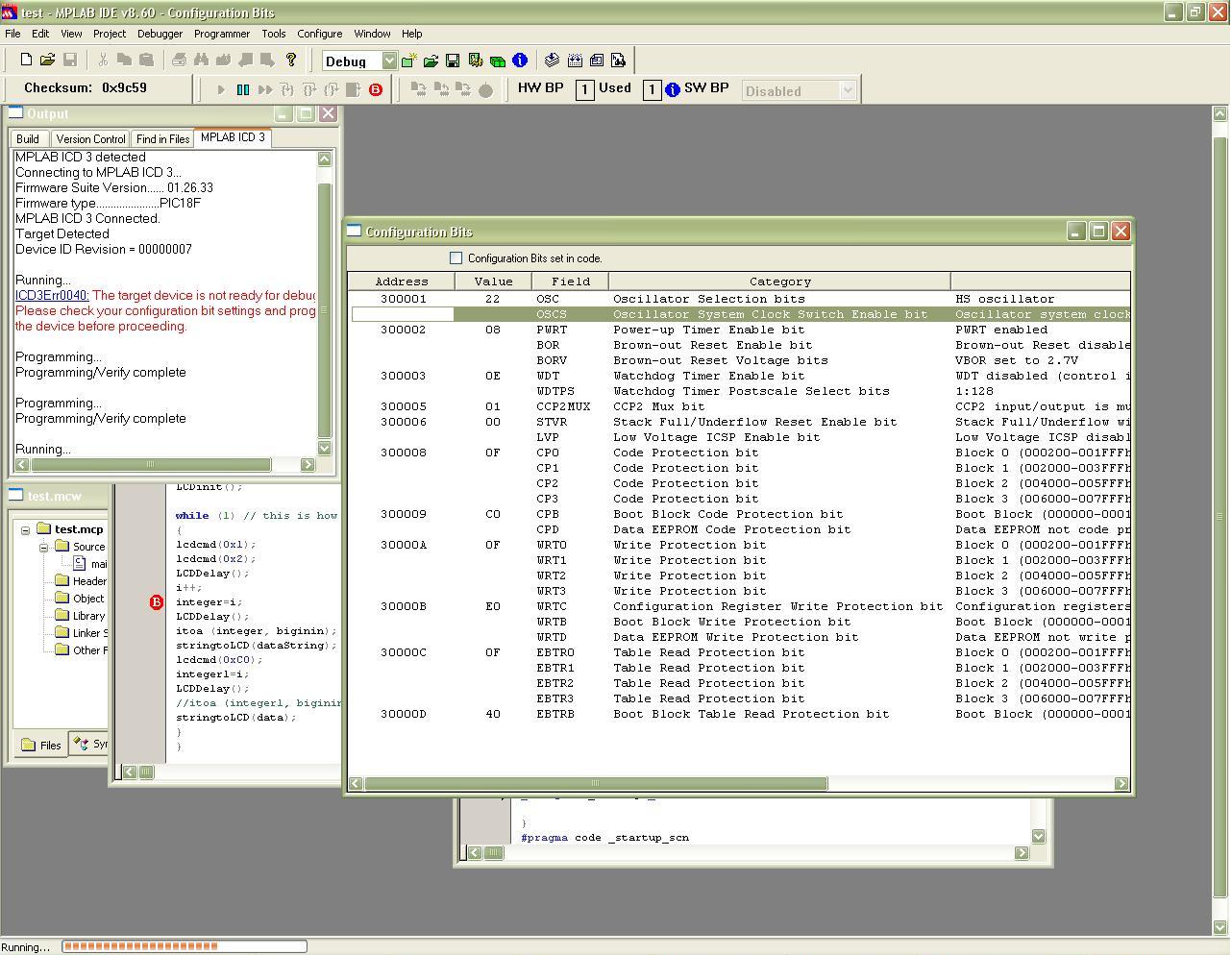
MPLAB ICD 3 detected
Connecting to MPLAB ICD 3...
Running self test...
Self test completed
Firmware Suite Version...... 01.26.33
Firmware type......................PIC18F
MPLAB ICD 3 Connected.
Target Detected
Device ID Revision = 00000007

Programming...
Programming/Verify complete

Running...
ICD3Err0040: The target device is not ready for debugging.
Please check your configuration bit settings and program
the device before proceeding.

I check my configuration bits. I read in the section Debug Failure Actions (Troubleshooting>Error Messages> Debug Failure Actions) in the MPLAB ICD3 help. But i don't know what i am doing wrong.


Does someone know why i can't program my pic?
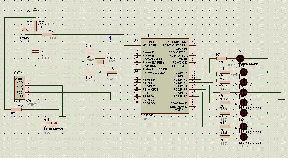
 

You have to program it in Programmer mode not Debugger mode ~~
 

I also program it in Programmer mode, but when i went in debugger mode and press the run button, i have the same problem.
 

Hi,

Have you check to make sure you are compiling the code with a build configuration of 'debug' ? If you are using Microchip's IDE, check menu Project => Build Configuration and make sure 'Debug' is checked not 'Release.' If you want to debug code, you must ensure that you've put the hooks in for the ICD3. Compiling the code with a build configuration of 'Release' removes these hooks. Also make sure your oscillator option is configured correctly to use the ICD3. Check Microchip's **broken link removed** for additional docs and tutorials. I hope this info help's in your prusuit!

Good Luck
 

HELLO bigdogguru
I have check that with 'Debug'
Also i chech and my oscillator and i think its ok. I use 20MHz so i have to put in HS mode. I change the oscillator with 10MHz in HS mode but nothing. I change the mode to XT just for test but nothing.
 

Hi,

Zip the whole project up and either send me a PM with it as an attachment or post a reply with the attachment. I need to know what version of Microchip IDE and Compiler, most likely something like v8.xx for both. Also are you using a development board, if so what model is it. I can recreate it here and send it back to you with the correct configuration settings in the project file.

Thanks,
 

Hi,

I read your PM, however I was unable to view any of the pix that you upload into your album. Are you sure your album exists? Anyway after reading the following:

I don't know if i make right the conection to MCLR I think R6 it does't need because i have R7. The RJ-8 female connector is conected with RJ-11 caple and ICD

This is most likely your problem. There are five required lines for ICSP, R6 (Clock Input), R7 (Data I/O), MCLR (Program Mode Select & Program Voltage), Vdd (Power Supply) and Vss (Ground). Without these lines correctly connected programming and debugging will not succeed! I have included two pixs of the PICDEM2 Plus Schematics which I used to test your code with a PIC18F452 and have the entire project zipped up if you need it. I have also circled the areas of interest in red, pay special attention to the order of the ICD lines.

Ensure you have the proper connection with the ICD3 and PIC18F452 and we'll proceed from there.

Good Luck,
 

Attachments

  • PICDEM2Plus1.jpg
    PICDEM2Plus1.jpg
    93.6 KB · Views: 128
  • PICDEM2Plus2.jpg
    PICDEM2Plus2.jpg
    105.1 KB · Views: 129
Hi bigdogguru

Thank you very much for your help. I will check the photos that you send me and correct my circuit.

I upload a photo of my circuit and my project in ZIP. From your photos i understand that i don't need resistor R6=10KΩ.

I have read that, the diode D5 (1N4002), it need to discharge the capacitor
quickly when VDD powers down. (datasheet page 28 of pdf)

Also i think that i need the resistor R10=1KΩ. From datasheet (page 19 of pdf) say that series resistor (RS) may be required for AT strip cut crystals. I am not sure for the type of my crystal, but when i take it out or when i put R=100Ω it makes me another problem. ( I think i have error with memory or something like that i am not sure)

Can you send me the project that you made with my code and with PIC18F452 to try it please?


Here is my project in zip
View attachment example led c18.rar
 
Last edited:

Hi
I take out the resistors R6 and R10 from my circuit and i try from other Computer to program my pic. It didn't show me the error "ICD3Err0040" and when i press the button RUN it start running but it took more than 30 minutes and i stop it. I try again but the same. Here is the photo:


When i try it again to my computer i saw again the error "ICD3Err0040"
 

its OSC0 and OSC1? by default it is OSC0 and OSC1 :) you connect to OSC1 and OSC 2?
 

Hello john blue

I connect to OSC1 and OSC 2 as you can see in my circuit

its OSC0 and OSC1? by default it is OSC0 and OSC1

Sorry i don't understand this.
I make the connection as it show in datasheet (page 19 of pdf). I don't find something about OSC0.
 

Status
Not open for further replies.

Similar threads

Part and Inventory Search

Welcome to EDABoard.com

Sponsor

Back
Top