Rajesh_ece
Newbie level 4
Hi
This is my code for segment lcd module
LCDPS=0x3A;
LCDCON=0x83;
LCDREF=0xC0;
LCDCST=0x07;
LCDSE0=0xFF;
LCDSE1=0X03;
LCDRL=0x50;//0x50;//0x51;/
clearAllSegments();
SEG3_A=1; // comm1
SEG3_D=0; // com2
SEG3_E=0; // com3
SEG3_F=0; // com 4
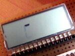
i'am trying to turn segment A for the 3rd digit but other segments which is connected on same segment pin
which is D,E,F were slightly glow which makes unable to read clearly.
then i adjusted the above code for low power and minimum contrast.
but it does n't helps me...........
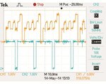
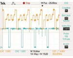
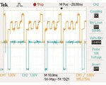
here i had attached screen short of scope output from that you can see the com output from was good
but segment output was not as like in datasheet( it was a rar file attached)


Real picture of lCD Problem.
**broken link removed**
please help me to solve this problem
thanks and regards
Rajesh
This is my code for segment lcd module
LCDPS=0x3A;
LCDCON=0x83;
LCDREF=0xC0;
LCDCST=0x07;
LCDSE0=0xFF;
LCDSE1=0X03;
LCDRL=0x50;//0x50;//0x51;/
clearAllSegments();
SEG3_A=1; // comm1
SEG3_D=0; // com2
SEG3_E=0; // com3
SEG3_F=0; // com 4
i'am trying to turn segment A for the 3rd digit but other segments which is connected on same segment pin
which is D,E,F were slightly glow which makes unable to read clearly.
then i adjusted the above code for low power and minimum contrast.
but it does n't helps me...........
here i had attached screen short of scope output from that you can see the com output from was good
but segment output was not as like in datasheet( it was a rar file attached)


Real picture of lCD Problem.
**broken link removed**

please help me to solve this problem
thanks and regards
Rajesh