Continue to Site

Welcome to EDAboard.com

Welcome to our site! EDAboard.com is an international Electronics Discussion Forum focused on EDA software, circuits, schematics, books, theory, papers, asic, pld, 8051, DSP, Network, RF, Analog Design, PCB, Service Manuals... and a whole lot more! To participate you need to register. Registration is free. Click here to register now.

problem on oscillator w/ spread spectrum for PWM controller

Status
Not open for further replies.

allennlowaton

Full Member level 5
Joined
Oct 5, 2009
Messages
247
Helped
3
Reputation
6
Reaction score
3
Trophy points
1,298
Location
Taiwan
Activity points
3,064
Good day guys!!!

Your ideas are highly needed regarding this matter..
the circuit shown is an oscillator with frequency spread that will be used for a PWM controller.

I had a simulation on the circuit shown. At first, I used an ideal clock for the two NMOS which paralleled the capacitors. I obtained a reasonable output.

34_1282755014.jpg


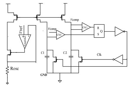
NOTE: THE OTHER VCOMP IS NOT CONNECTED WITH THE OTHER INPUT ON CM2

The problem comes in when I completed the loop. Node on capacitor1 (C1) don't charge yet node on C2 don't discharge too.

Please share your idea on what to do.

Thank you.
 

Remove the inverter from FF output to enable the oscillator.

But I don't see a spread spectrum property with it.
 
thank you FvM..
do you mean, I will going to remove the two inverters after the RS?

But those inverters will supply pulses to the two NMOS.
I don't understand.
 

thank you and I'm sorry. I made a mistake.
I had tried removing it but still no oscillation took place.
 

Have you tried to put initial conditions on your C1 and C2?
 
Have you tried to put initial conditions on your C1 and C2?

yes..I also put initial conditions on the capacitors, on other simulations I put C1 with 1.8v and C2 with 0V and interchanged them also. But I don't obtain a correct output. In this circuit. I just used a N-type input pair two stage OP-amp as my comparator. Do you guys think, its just ok?
 

If it were me, I'd start with an oscillator you know works,
and then worry about making it noisy.

However I am also presently not a fan of "spread spectrum"
clocking, because you can end up adding so much pulse
width jitter that your output quality-of-regulation suffers.
Keep an eye on that.
 
thank you ****_freebird...
your comment really made me think more...
I was tasked to find an improvement in a PWM controller IC needed for an LED driver and I believe EMI reduction
is a good thing to looked unto.
yes..its true, there's a trade off between the jitter and EMI...
 

If your EMI concern is strictly "radio", amplitude-not-to-exceed
within any given slot, spreading can help you "game the system".

But every individual pulse will emit the same impulse energy, to
be received by neighbors, regardless of how the rate wanders.
You would have to understand your sensitivities to determine
whether what might be displayed on a spectrum analyzer, is
really the interesting part of the story. Just like transient analysis
and AC small signal analysis can show you the same thing if you
are looking at gain/phase with a small sinusoidal stimulus, but
disagree quite a bit when things are not so ideal.

In my view, spread spectrum clocking is a way to pass standards
tests, but not a cure for envelope-of-noise or spike type issues.
 
thanks ****_freebird..
your comments are so useful.
can I ask you a very straightforward question? since I am still in the
starting phase of this study, is it recommended for me to shift to another area of focus?
I have a strong feeling that you are a knowledgeable man regarding with this.
thank you very much...
 

Status
Not open for further replies.

Similar threads

Part and Inventory Search

Welcome to EDABoard.com

Sponsor

Back
Top