Continue to Site

Welcome to EDAboard.com

Welcome to our site! EDAboard.com is an international Electronics Discussion Forum focused on EDA software, circuits, schematics, books, theory, papers, asic, pld, 8051, DSP, Network, RF, Analog Design, PCB, Service Manuals... and a whole lot more! To participate you need to register. Registration is free. Click here to register now.

Problem in timer 1 in pic16f877A

Status
Not open for further replies.

selva murugesan

Advanced Member level 4
Joined
Mar 30, 2012
Messages
116
Helped
2
Reputation
4
Reaction score
1
Trophy points
1,298
Activity points
2,007
hello experts,

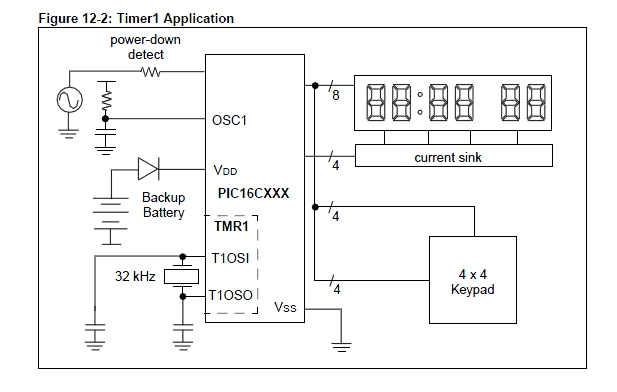
I am confused about the timer 1 registers in pic16f877a. What is the need for external oscillator in timer.How to select the internal oscillator turn on? I want code for one second delay.
 

6.2 Timer1 Oscillator
A crystal oscillator circuit is built in between pins T1OSI(input) and T1OSO (amplifier output). It is enabled bysetting control bit T1OSCEN (T1CON<3>). The oscilla-tor is a low power oscillator rated up to 200 kHz. It willcontinue to run during SLEEP. It is primarily intendedfor a 32 kHz crystal. Table 6-1 shows the capacitorselection for the Timer1 oscillator.

so you need to put a 32khz crystal between pins 15 and 16 and 2 x 33pF capacitors to the ground.
 

thanks Kripton2035

I would like to use the primary crystal (20Mhz) for timer1 base and micro-controller itself.Is that any problem
 

Hi,

As Kripton said, you typically use an external 32k crystal to generate a 1 second delay.
A 32k signal divides down exactly to 1 second ;the max Timer1 can divide 32k down to is 2 seconds

You can select Timer1 to operate from your main crystal of 20mhz by using the correct control bit

TMR1CS: Timer1 Clock Source Select bit
1= External clock from pin RC0/T1OSO/T1CKI (on the rising edge)
0= Internal clock (FOSC/4)

However 20mhz / 4 does not divide down to exactly 1 second if you are after accurate timings ..?
Also you will have to include a secondary counter in your ISR to count how many times Timer1 has to roll over to produce a 1 second delay.


Have you considered using a software delay of 1 second instead ?
 

thanks wp100,

But ,I made it.first of all I used the timer1 for display the time. It is not delay (NOP) function. How can i turn off the timer 1 ISR.? I know that, disable the interrupt enable should be turn off the timer1. Is there any other way?
 

+1 to use a software delay function for a 1 second delay.
except if it must be very precise in case you need the 32KHz crystal (or a maxim DS3232 chip)

you wont be able to generate a 1 sec delay with interrupt with a 20MHz oscillator : it's too fast
you will need to count in software many cycles of interrupts.
better use a 32KHz crystal, or a delayms(1000) function.
 

thanks wp100,

But ,I made it.first of all I used the timer1 for display the time. It is not delay (NOP) function. How can i turn off the timer 1 ISR.? I know that, disable the interrupt enable should be turn off the timer1. Is there any other way?


Hi,


There is no need to actually stop Timer1 you simply clear the Timer1 Interrupt Flag

In the ISR you would do something like this.

Code:
isrtm1	btfsc PIR1,TMR1IF		; timer1 overflow int
	goto	tm1over		        ; timer1 has overflowed
	goto 	hisrend				; not tmr1 overflow - error - go back

tm1over incf        COUNTER                    ; increment counter,  number of times TM1 has overflowed
	[B]bcf	PIR1,TMR1IF		; reset timer1[/B]

If you want to stop Timer1 from Interrupting then just turn the Timer1 interrupt bit off.
 

if you want to display an almost accurate time, it's better to use a 32khz crystal and timer1 interrupt
it's made for this purpose !
 

hi Kripton2035

thanks. I agree with you,now I made it with help of (20Mhz) main crystal.I want to change it into 32khz. can you Guide me for this?coding as well as harware(GND connection)?
 

you leave the 20mhz crystal where it is and you add a 32khz crystal to pins 15 and 16 and 2 x 33pF capacitors from pins 15-16 to the ground. then you "play" with timer1 interrupts
 

Reference: PICmicro Mid-Range MCU Family Reference Manual, Section: 12.6 Timer1 Oscillator, Page: 12-7
Timer1 Oscillator

A crystal oscillator circuit is built in between pins T1OSI (input) and T1OSO (amplifier output). It
is enabled by setting the T1OSCEN control bit (T1CON<3>). The oscillator is a low power
oscillator, rated up to 200 kHz operation. It will continue to run during SLEEP. It is primarily
intended for a 32 kHz crystal, which is an ideal frequency for real-time keeping. Table 12-1 shows
the capacitor selection for the Timer1 oscillator.

The Timer1 oscillator is identical to the LP oscillator. The user must provide a software time delay
to ensure proper oscillator start-up.

Note: This allows the counter to operate (increment) when the device is in sleep mode,
which allows Timer1 to be used as a real-time clock.


BigDog
 

Status
Not open for further replies.

Similar threads

Part and Inventory Search

Welcome to EDABoard.com

Sponsor

Back
Top