Dines
Newbie level 5
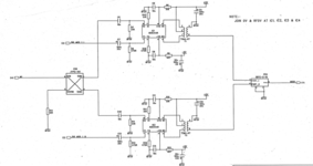
We are implementing the below circuit as follows. We are giving M1 at 108 MHz and the splitting SUM 1 at 3 dB with 90 deg phase shift and SUM 1 at 3 dB with 0 degree.
At the input of SIG_MOD_1_I at 1.348 KHz with zero degree and the SIG_MOD_I_Q at 1.348 KHz with 90 degree phase. It is driving in to AD834AR (four quadrant multiplier).
We are trying to measure the phase difference in the Vector network analyzer at 6th pin (TCM4-6T) but we are getting constantly fluctuate phase or not stable to measure. In theoretically it should be same phase either 0 or 90 degree at the input of power divider (SBTC-2-10) to combine.
Kindly let us know how to measure the measure the phase at pin 6 from TCM4-6T and what output should expect ?