Continue to Site

Welcome to EDAboard.com

Welcome to our site! EDAboard.com is an international Electronics Discussion Forum focused on EDA software, circuits, schematics, books, theory, papers, asic, pld, 8051, DSP, Network, RF, Analog Design, PCB, Service Manuals... and a whole lot more! To participate you need to register. Registration is free. Click here to register now.

problem in checking status of Input bits of pic microcontroller

Status
Not open for further replies.

mashal8050

Newbie level 6
Newbie level 6
Joined
Jun 5, 2012
Messages
13
Helped
0
Reputation
0
Reaction score
0
Trophy points
1,281
Visit site
Activity points
1,366
hi all members
I am using pic16f877 with 8Mhz clock frequency. I am facing problem in checking the status of an input pin..
My code is
LOGIC
- when RA0 = high then RB0 = 1
-when RA0 = low then it checks if RA1 = high if yes then RB0=0 and RB1=1, if not then RB2=1.
CODE in MikroC

Code:
void main() 
{

TRISA=0x07;
TRISB=0;

while(1)
	{
		if(RA0==1)
		{
			PORTB.F0 = 1;
			PORTB.F1 = 0;
			PORTB.F2 = 0;
		}
		else if(RA0==0)
		{
			if(RA1==1)
			{
				PORTB.F0 = 0;
				PORTB.F1 = 1;
				PORTB.F2 = 0;
			}
			else
                        {
                                PORTB.F0 = 0;
                                PORTB.F1 = 0;
				PORTB.F2 = 1;
			}
		}

	}
}
but in proteus nothing happens according to the conditions. Proteus figure is as below:
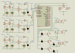
SWITCHING.png
any help would be highly appreciated.
Regards:grin:
 
Last edited by a moderator:

Try adding "ADCON1 = 0x06;" at the start of main(). The 16F877 defaults to analog inputs but you are expecting digital.

It's also a good idea to indent the listing to make it easier to follow.

Brian.
 

hey thanks .. but adding ADCON1 = 0x06; had no effect on simulation
and kindly if u can elaborate what u meant by indent the listing
regards
 

Indentation makes it look like this:

Code:
void main()
{
	ADCON1=0x06;
	TRISA=0x07;
	TRISB=0;

	while(1)
	{
		if(RA0==1)
		{
			PORTB.F0 = 1;
			PORTB.F1 = 0;
			PORTB.F2 = 0;
		}
		else if(RA0==0)
		{
			if(RA1==1)
			{
				PORTB.F0 = 0;
				PORTB.F1 = 1;
				PORTB.F2 = 0;
			}
			else
			{
				PORTB.F0 = 0;
				PORTB.F1 = 0;
				PORTB.F2 = 1;
			}
		}
	}
}

which is much easier to follow. Please show the remaining code, perhaps you have the configuration bits set wrongly.

Brian.
 
this is the whole code and i haven't configured any bit i thought they can be accessed directly in main()
 

No, I'm afraid there is a bit more to it than just the main() code.

Before the processor will run at all it has to be configured so there is no point in trying to configure itself in the program! You have to tell it things like what type of clock is being used, it's frequency, whether the watchdog is in use and some start-up settings. If you look in the data sheet in section 14 it will explain what you have to do.

Brian.
 
You also have to configute CMCON register. CMCON = 0x07;

I see that you have used 12V relay in Proteus. So, you have to use a 12V supply for relay. Use a battery of 12V or change the relay voltage to 5V.
 
Last edited:

as i am using mikroC I selected 4Mhz clock frequency !
also the problems i was facing were solved and Proteus circuit was working by doing following:
-removing the comparator circuits and replacing pull up-resistors
are you referring that for hardware implementation i have to configure microcontroller through operations mantioned in section 14 of the data sheet

and thanks brother for your time and help v much appreciated
regards Mashal :smile:

- - - Updated - - -

- - - Updated - - -

hi
I had connected relay to 12V and it is working..
and why to configure CMCON register ??
 

In real life you have to configure it before it will work. Sometimes, and it appears Proteus is guilty, the simulation just assumes it is configured properly.

It isn't strictly necessary to use CMCON but it is good practice to do so. In fact it's a good idea to configure all the registers, especially those that would stop it working properly. Although it might work with the default settings when first powered up, if the watchdog timer causes a reset there is no guarantee the values it will restart with will be suitable. By setting all the registers to good values at the start of the program you can be sure it will run properly no matter what caused the last reset.

Brian.
 
Status
Not open for further replies.

Similar threads

Part and Inventory Search

Welcome to EDABoard.com

Sponsor

Back
Top