Continue to Site

Welcome to EDAboard.com

Welcome to our site! EDAboard.com is an international Electronics Discussion Forum focused on EDA software, circuits, schematics, books, theory, papers, asic, pld, 8051, DSP, Network, RF, Analog Design, PCB, Service Manuals... and a whole lot more! To participate you need to register. Registration is free. Click here to register now.

Powering Solenoid using PWM from Func. Gen

Status
Not open for further replies.

mazahyr

Junior Member level 2
Joined
Apr 8, 2014
Messages
22
Helped
0
Reputation
0
Reaction score
0
Trophy points
1
Location
Huddersfield, England
Activity points
182
Hi All,

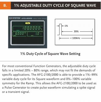
A very quick and daft kind of query. I'm trying to actuate a solenoid with PWM. I tried searching about it but couldn't get exactly what I want. Its quite simple though. I've got a function generator, GwInstek AG-2005. I want to run this solenoid at certain parameters. I simply hooked it up to the output of the Func Gen thinking it would start pulsing the solenoid but I was wrong. Something keeps telling me that I need an external power going into the solenoid to run it.

Any help regarding connecting the solenoid would be much appreciated.

Thanks.
 

First question: How much current does the solenoid need?
Second question: How much current can your function generator supply?
Third question: are you trying to damage your function generator?
 

First measure the coil DC resistance and make a transistor switch either high side (P type or PNP) or low side (N type or NPN) have an effective series resistance that is < few% of coil resistance and to an antiparallel diode capable or carrying the current surge when the solenoid switches off. That will be across the coil in opposite polarity.

Without this you can damage your generator with overvoltage kickback. The generator is most likely 50 Ohms and your coil a few ohms so you need a switch than can drop <5% of the voltage applied at the coil resistance for good low impedance drive.
 

Cheers for the quick response.

1st: Solenoids can draw upto 1.2A @ 6VDC not PWM
2nd: No Idea can't find it on spec sheet.
3rd: No intentions as of yet! :)

Idea is quite simply get the solenoid working. I've got all the specs i.e chop duty, frequency & duty cycle. Can't figure out how to Power it. Any help would be much appreciated. Thanks!
 

As noted in #3, you'll need a transistor to control that solenoid.

But why pwm? Are you trying to control the solenoid current?
 

Solenoids are like linear motors except with end stops and in some cases springs to provide passive return force.

In the first case, like a rotary DC motor , you need to drive it with a switch of much lower resistance than the coil resistance.
If your voltage is much higher than required, that usually implies you need more current than you expected, which obviously 50 Ohm generator cannot supply, But any clock can be used a switched gate driver for small loads. AS long as the frequency is high enough to average out the electromotive forces and not cause chattering and yet not too high that it causes eddy current losses in the magnetic material, it will work. It works somewhat like a continuous-mode SMPS in buck step-down mode.

For the case of a solenoid with a stiff return spring, these are often driven in half sine wave rectified mode such as 120Vac rated solenoids with a single series diode rated for coil current. The spring mass is designed to resonate at the driving frequency such as 50/60 Hz. When the mass is a plastic coated magnet in a tube connected to a diaphragm valve, now you a fluid pump. THis is how they make high pressure water pumps for expresso machines or small electric air pumps.
 

As noted in #3, you'll need a transistor to control that solenoid.

But why pwm? Are you trying to control the solenoid current?

It is to be used as a dosing valve running at a certain frequency which would determine the duration of valve opening and closing. The speed or in-rush current is controlled using chop-duty.


How are you doing the PWM with the generator?

Something I'm trying to find out my self.

- - - Updated - - -

As noted in #3, you'll need a transistor to control that solenoid.

But why pwm? Are you trying to control the solenoid current?

Effectively yes!
 

Quote Originally Posted by crutschow ----
How are you doing the PWM with the generator?

Something I'm trying to find out my self.
If the function generator allows control of the pulse-width independent of the frequency or the frequency independent of the pulse-width, then you just vary one or the other (but not both) to control the PWM duty-cycle.
 

I still don't quite understand your application. Are you trying to open and close a valve rapidly? How fast? Maybe a solenoid is not what you want, but rather a linear actuator or servo.
 

Right to cut the chase short I'm trying to validate a solenoid which works with a pre-programmed ECU/MCU. I'm trying to replicate the same conditions to understand the characteristics i.e. currents and temperature. I was under an impression that If I'm able to generate that wave form with the set parameters i.e. Vpp, Duty, Frequency, Square Wave etc I'd be able to operate it. But the simplicity of this setup kept me questioning the theory behind it. And when I did try this daft setup it didn't work, for obvious reasons.

Now tools that I have in hand include the mentioned Generator for wave form parameters, what can you guys suggest that would be useful to build/replicate the PWM conditions? Mentioned is a detailed spec of my solenoid.

Voltage range: 8 to 32 VDC [PWM control]
Pull-in current: 2.0 Amps DC [RMS] maximum
Hold current: 1.2 Amps DC [RMS] maximum
Coil resistance (25℃): 5.2 ± 8% ohms
Coil inductance: 15.0 mH
 

It looks like you need a power supply of at least 8V with a peak current capacity of 2A, connect this to your solenoid via a power transistor, connect a reversed biased diode across the coil to protect the transistor. Connect your generator (set to minimum frequency = 1 HZ 50/50 mark space) to the base and emitter of the transistor. This should start the solenoid pulsing.
As you increase the frequency of the PWM, you have to increase the power supply voltage as the current take a certain time to flow (T = 15 X 5.2 X 10^-3 ~ 75 mS), altering the mark/space ratio will alter the stroke of the plunger.
Frank
 
Last edited:

stumbled across this

3646249000_1402389888.jpg
 

It looks like you need a power supply of at least 8V with a peak current capacity of 2A, connect this to your solenoid via a power transistor. Connect your generator (set to minimum frequency = 1 HZ 50/50 mark space) to the base and emitter of the transistor. This should start the solenoid pulsing.
As you increase the frequency of the PWM, you have to increase the power supply voltage as the current take a certain time to flow (T = 15 X 5.2 X 10^-3 ~ 75 mS), altering the mark/space ratio will alter the stroke of the plunger.
Frank

Exactly what I had in my mind..didn't know how to hook all of them up. Thanks!
Any suggested power transistor that I should use?
 

Hello fellow helpers,

After looking up some PWM configurations I got something that might do the job any comments?


My understanding of the operation of the solenoid is, do correct me if I'm wrong, that when you initially apply a higher voltage i.e +24V, in my case, and drop it down to something +16V. The higher voltage provides inrush current opening the valve/pulling the armature and then lower voltage level would hold the valve/armature. Now this inrush current at higher voltage needs to be quick enough to prevent coil from getting hot(eddy current losses) hence PWM is used to vary this in milliseconds.

I'm very close to getting this running just need to get the right circuit for the right spec.

Thanks.
 

That's interesting, your quote did not show my additional remark about the anti back EMF diode that I added in an edit. Bug on site?
To get the current flowing into the inductance of the coil to flow as quickly as possible, it should be driven from a constant current generator, which does as per your description, i.e. high initial volts that fall when the solenoid finally pulls in. Your circuit does this. It does not generate volts though, so you need a supply sufficiently high for the effect to be seen. This is why I suggested starting of at 1 HZ, so 8V will work. Because there are lots of unknown variables (mass of plunger, resonant frequency of the spring. . ), its easiest to actually build a prototype and run it and see, how the solenoid behaves at different PWM frequencies and plot against supply voltage and figure out what voltage you need for you max operating speed.
Your circuit show the diode connected via a switch, opening the switch will result in large voltage pulses being applied to the drain of the FET, which may break it down.
I am old fashioned and would use a 2N3055 (I have a boxful of them!). A FET would be better. I am sure that one of the modern gentlemen on this site could recommend something.
Frank

Cheers for the reply Frank.

Just had this knowledge cringe, my knowledge is solely based on application and a bit of O'level stuff. For control circuitry I'm fine as electronics is my major. Now this cringe is about me mixing duty cycles. Can anyone here be able to help me get a better understanding of it. What I understand as of now is that (On-time)/(Total Time) x 100.

But in solenoids we have three stages. Pull-In, Hold and Off the Pull-In and Hold add-up to make On-time isn't it? If this is true then I'm having trouble understanding this characteristic profile.

8250539400_1402478618.jpg
 

But in solenoids we have three stages. Pull-In, Hold and Off the Pull-In and Hold add-up to make On-time isn't it? If this is true then I'm having trouble understanding this characteristic profile.

8250539400_1402478618.jpg

What the table say is that you activate the solenoid with a 20ms pulse, and hold it with a 0.875ms pulse every 2.5ms, reducing the hold current to 35% of the pull current. In OFF mode you don't do anything.
 
What the table say is that you activate the solenoid with a 20ms pulse, and hold it with a 0.875ms pulse every 2.5ms, reducing the hold current to 35% of the pull current. In OFF mode you don't do anything.

Thanks a lot Gorgon, can you help me understand this bit

20ms pulse, and hold it with a 0.875ms pulse every 2.5ms, reducing the hold current to 35% of the pull current

How did you work out the timings?

Sorry worked it out makes sense now.

Now how would it work with this profile?

Its not 100% duty cycle and both timings don't add up to 100% Is it suggesting that there is Pull-In for 50% Hold for 17% and then Off for the rest of the time?

The reasoning I can think of for this OFF timing would be heating and exposure to high currents or some kind of cool-off time period.?
 

Attachments

  • Varied Duty.JPG
    Varied Duty.JPG
    16.7 KB · Views: 61
Last edited:

Status
Not open for further replies.

Similar threads

Part and Inventory Search

Welcome to EDABoard.com

Sponsor

Back
Top