Continue to Site

Welcome to EDAboard.com

Welcome to our site! EDAboard.com is an international Electronics Discussion Forum focused on EDA software, circuits, schematics, books, theory, papers, asic, pld, 8051, DSP, Network, RF, Analog Design, PCB, Service Manuals... and a whole lot more! To participate you need to register. Registration is free. Click here to register now.

Powering a Fluorescent Bulb?

Status
Not open for further replies.

ConfusedCircuitBoy

Newbie level 4
Joined
Apr 2, 2011
Messages
5
Helped
0
Reputation
0
Reaction score
0
Trophy points
1,281
Activity points
1,335
Hi,

Thanks a lot for reading this message. We've never worked with fluorescent bulbs before, so we're having a lot of trouble...

We're trying to power this bulb:
**broken link removed**

It apparently requires 35V AC to power it.

We're planning on having USB (5V, 100-500mA output) charge a battery. We haven't figured out the specs of the battery yet, but we're thinking it will be 3.5-6V.

We need to take the voltage from the battery, convert it to 35V AC to power the bulb. How can we do this? Would the battery simply run on 35V DC? That might be a lot simpler since the battery is in DC and we'd just need some sort of boost converter.

If we do need 35V AC to power the bulb, can we use some circuit that simulates AC? Our initial design (which is not good) is attached.
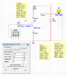
BulbDesign1.PNG

Any help would be really appreciated. If there are parts available that do what we need that you can guide us to, that would be extremely helpful.
Thanks so much!!!
 

Its a little more complicated than that. The 35V is not the operating voltage you provide for the lamp, if you simply put 35V across it nothing would happen. The voltage is measured across the lamp when it is conducting and passing 180mA. You need to provide a higher voltage so you can stabilize the current at 180mA, then you should see 35V across the end of the tube. However, before it will conduct you have to provide sufficient voltage for the tube to 'strike' and that might be 200V or more. When lit it might work on DC but you would probably find it lit up at one end rather than along its whole length.

Brian.
 

welcome to EDAboard.
such a circuit needs higher volateg than 35V AC.
please check some emergency lamps ike SUNKA make , a chinse brand , i suppose.
the high voltage AC used there measures 150 to 200V ?at 50KHz , may be.
thus you need to create a 50KHz oscillator and have a booster circuit with a ferrite cored transformer.

then these Philips lamps would generally contain a gas filled starter inside the central plastic chamber.
when such bulbs are needed to be used with electronic HF converters, perhaps you have to replace that with a 330K resistor and 2200pF/400V capacitor in parallel.
all the best
 

This is not so simple problem

Here is some data about this lamp

Benefits
• Integral starter cuts installation wiring costs and permits use of small
chose ballasts
• Better for the environment with ALTO lamp technology
• Available in variable color temperatures
Features
• High Lamp Efficacy
• 10,000 Hour Rated Average Life*
• Designed for Use with Magnetic Ballasts
• Integral Starter in Base
• ALTO® Lamp Technology

There are two things to check about when connecting this lamp
1. Designed for Use with Magnetic Ballasts
2. Integral Starter in Base

So I think this lamp need 220V supply for starter circuit and some
inductive component for limiting the current when lamp is working.

Fluorecent tube needs high voltage pulse(s) for ignition and when tube becomes
conductive , impedance goes low and it needs some series component to keep
current in right level.

Look these texts & circuits:

12 Volt fluorescent lamp drivers

File:Fluorescent Light.svg - Wikimedia Commons

**broken link removed**
 
Last edited:

Thank you all very much for your answers!

So what do you think is the best way to go about this? We're working with the USB powered battery and a microcontroller (MSP launchpad). We can order different parts as necessary, but we can't use power from the outlet or other sources (it must be a rechargeable battery).

We've been reading about ballasts and starters, but there is no clear indication of what these do and how we can use them to help us solve the problem.

Thanks so much for your time and any of your suggestions (especially involving circuit diagrams) would be extremely helpful in getting us going in the right direction...
 

First, realize that the MAXIMUM current you can draw from a USB port, if it meets full specification is 500mA at 5V, that sets the maximum power you have available at 2.5W. This means that no matter what battery or circuitry you use, you can never keep the lamp running continuously. The best you will be able to do is spend a lot of time charging the battery and little time seeing the lamp light up.

The ballast is just a device for limiting how much current can flow, it works like a resistor but uses reactive properties instead of resistive to keep the power loss as small as possible. for example, assuming the lamp needs 200V to ignite, if you left the 200V there after it started to conduct it would probably explode in less than a second. When it conducts, it presents almost a short circuit across the voltage and so much current would flow that the heat generated would be enormous. The ballast is there to limit the current to a safe level. You could use a resistor but if it had to drop 200-35V at 180mA it would dissipate 30W of heat so it would be physically larger than the lamp itself! In some systems the ballast is also used to create a high voltage spike to help ignite the gas in the lamp.

The starter is a device to allow the high voltage to ignite the tube but then switch the ballast into circuit as soon as current flows. I'm not sure what the internal starter in the Philips lamp does but in a conventional fluorescent lamp, it shorts out the ends of the tube, allowing current through the heater coils then removes the short so full voltage appears from end to end.

Brian.
 
Thank you again for your help.

We've decided to start looking at different bulbs instead. Our actual application is using UVC light to kill bacteria. Therefore, we only need the bulb to be on for approximately 120 seconds every 4-6 hours.

We're thinking about using this kit to help us build and power the bulb:
**broken link removed**

Now what we need to figure out is what the best way to utilize USB to power a battery which can then be converted to 12V DC to power the inverter from the kit. What kind of circuits and batteries should we be looking at?

THANKS A LOT FOR THE HELP! :)
 

That is a far more 'doable' project. what you need is a 5V to 14V inverter and a 12V rechargeable cell with maybe 2AH capacity. There are many designs for boost inverters if you search for them or you can buy small ready-built modules to do the job. You will have to limit the charging current so the USB port isn't overloaded but with such a short discharge period and long recharge period that shouldn't be a problem.

I have to ask though - why are you restricted to using a USB port as the power source, it would be much easier to use a mains electrical supply, especially as the USB itself will have to be mains powered to last that long!

DO OBSERVE THE WARNING IN THE ADVERT - UV radiation can be very dangerous without anything being visibly wrong and the mercury in the tube is highly toxic.

Brian.
 
instead, perhaps the OP can have a working arrangement with 6V battery like any domestic emergency lights using CFL lamps.
he can have a linear power supply and charging arrangement for 6V battery at 8.4V limit. he can have an inverter to get the needed high voltage AC at 50KHZ or so, and manage to glow the tube. why have 12V transition and suffer the ills of double conversion etc?
I believe, simpler the circuitry, stable and efficient the system would be.
 
Last edited:

Thanks for your answers! We got the bulbs in and are able to power it with about 14.5V DC. I started building a boost converter, but I need help choosing the battery. I will be posting another thread shortly, so please look for it :)
 

Status
Not open for further replies.

Part and Inventory Search

Welcome to EDABoard.com

Sponsor

Back
Top